Pioneer ND-BC2 Owner's Manual - Page 6
Connection, <ENGLISH>, Specifications - install
 |
UPC - 012562856209
View all Pioneer ND-BC2 manuals
Add to My Manuals
Save this manual to your list of manuals |
Page 6 highlights
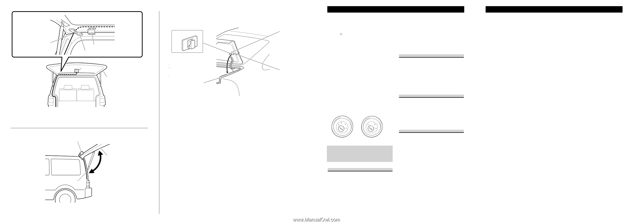
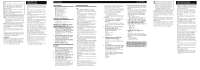
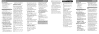
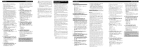
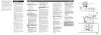
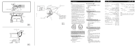
① Pull out from here ② Hinge ③ Harness cover ④ Rear view camera ⑤ Hatch ① Rear view camera Fig. 16 Abb. 16 ② Hatch ③ Cord Fig. 17 Abb. 17 ① Clamps ③ Rubber packing ② Waterproof pad ④ Make a U-shaped loop in the lead outside the rubber packing to prevent rainwater from flowing along the lead into the interior of the vehicle. Fig. 18 Abb. 18 Connection Note: • This unit is for vehicles with a 12-volt battery and negative grounding. Before installing it in a recreational vehicle, truck, or bus, check the battery voltage. • To avoid shorts in the electrical system, be sure to disconnect the battery cable before beginning installation. • Refer to the owner's manual for details on connecting the other units, then make connections correctly. • Secure the wiring with cable clamps or adhesive tape. To protect the wiring, wrap adhesive tape around them where they lie against metal parts. • Route and secure all wiring so it cannot touch any moving parts, such as the gear shift, handbrake and seat rails. Do not route wiring in places that get hot, such as near the heater outlet. If the insulation of the wiring melts or gets torn, there is a danger of the wiring short-circuiting to the vehicle body. • Do not shorten any leads. • Never feed power to other equipment by cutting the insu- lation of the power supply lead of the unit and tapping into the lead. The current capacity of the lead will be exceeded, causing over heating. • When replacing the fuse, be sure to only use a fuse of the rating prescribed on the fuse holder. • To minimize noise locate the TV antenna cable, radio antenna cable and RCA power supply cable as far away from each other as possible. • Connection to a TV with an RCA video input is possible, but confirm whether the TV you use has a reverse gear connection function. • If this unit is installed in a vehicle that does not have an ACC (accessory) position on the ignition switch, the red lead of the unit should be connected to a terminal coupled with ignition switch ON/OFF operations. If this is not done, the vehicle battery may be drained when you are away from the vehicle for several hours. F ACC O F O OF OF N STAR N STAR T T ACC position No ACC position • Cords for this product and those for other products may be different colors even if they have the same function. When connecting this product to another product, refer to the supplied manuals of both products and connect cords that have the same function. Connection sample (Fig. 14) ① Power supply unit ② Rear view camera connector ③ RCA power supply cable connector ④ Rear view camera Video input jack Connect to video input jack. ⑤ RCA pin Accessory power supply To electric terminal controlled by ignition switch (12 V DC) ON/OFF. ⑥ Red ⑦ Fuse (1A) Ground To vehicle (metal) body. ⑧ Black Cord installation (Fig. 15) ① Clamps ② Rear view camera ③ RCA power supply cable ④ Product with a video input jack (Hideaway unit etc.) ⑤ Power supply unit ⑥ Made with a rasp etc. ⑦ Scuff plate ⑧ Clamp ⑨ Waterproof plate Cord installation points (Fig. 16) • When pulling the cord out of the car, pull from the outer side of the hatch harness cover and hinge. ① Pull out from here ② Hinge ③ Harness cover ④ Rear view camera ⑤ Hatch After cord installation (Fig. 17, Fig. 18) • Open and close the hatch door slowly to confirm that the cord is not rubbing against the rim of the door. ① Rear view camera ② Hatch ③ Cord • When the rear view camera cord cannot be pulled out from the lower side due to the type of car. As shown in the figure 18, bend the cord into a U shape in front of the waterproof pad, making sure that rain water cannot enter the car by running down the cord. ① Clamps ② Waterproof pad ③ Rubber packing ④ Make a U-shaped loop in the lead outside the rubber packing to prevent rainwater from flowing along the lead into the interior of the vehicle. Specifications Power source 14.4 V DC (10.8 V to 15.1 V allowable) Grounding system Negative type Max. current consumption 120 mA Output video Mirror image (for rear view confirmation) Sensor 1/4-inch color CCD sensor No. of pixels ........ 492 (vertical) × 512 (horizontal) (Total no. of pixels: 270 000, effective no. of pixels roughly 250 000) Lens Wide-angle, focal length f = 1.53 mm, F value 2.8 Angle of view Horizontal: approx. 135º Vertical: approx. 100º IR cutoff filter (special filter for vehicle mounting) Provided Iris system Electronic iris Scanning system Interlace Synchronizing system ....... Internal synchronization Signal-to-noise ratio 40 dB or more (at the recommended intensity of illumination) Horizontal resolution Approx. 300 TV lines Illumination range .... Approx. 1.5 lux to 100 000 lux Image output 1 Vp-p (75 Ω) Operation temperature range 30ºC to +70ºC +22ºF to +158ºF Storage temperature range 40ºC to +85ºC -40ºF to +185ºF Dimensions Camera unit ... 27 (W) × 27 (H) × 26 (D) mm 1 (W) × 1 (H) × 1 (D) in. Power supply unit 70 (W) × 23 (H) × 35 (D) mm 2-3/4 (W) × 7/8 (H) × 1-3/8 (D) in. Weight Camera unit 150 g (0.3 lbs) (including the cable) Power supply unit 160 g (0.4 lbs) (including the power cord) Note: Specifications and the design are subject to possible modification without prior notice due to improvements.
-
 1
1 -
 2
2 -
 3
3 -
 4
4 -
 5
5 -
 6
6 -
 7
7 -
 8
8
 |
 |