Pioneer PDP-4350HD Owner's Manual - Page 53
Connecting other audio equipment
 |
View all Pioneer PDP-4350HD manuals
Add to My Manuals
Save this manual to your list of manuals |
Page 53 highlights
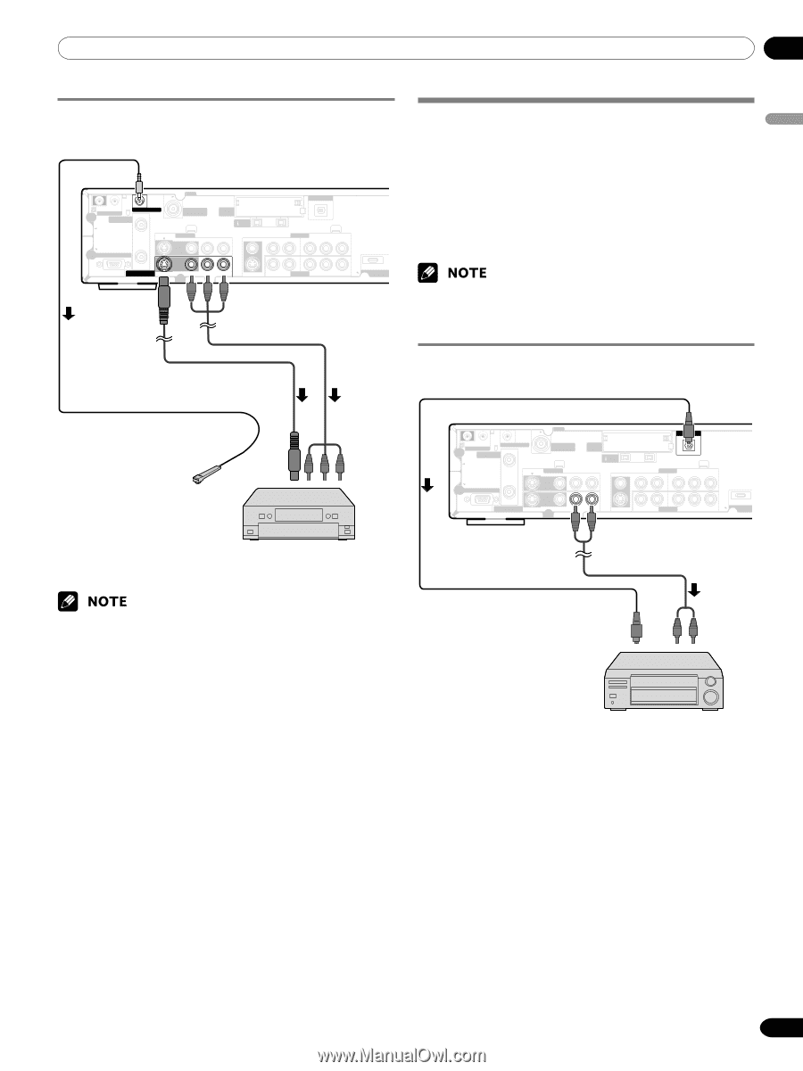
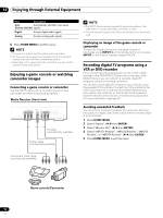
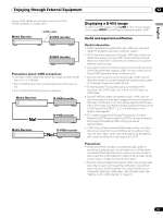
Enjoying through External Equipment 12 English Connecting a recorder Media Receiver (rear view) IN OUT VCR CONTROL CONTROL IN ANTENNA B ANTENNA/ CABLE A IN Cable CARD S-VIDEO INPUT 2 VIDEO R-AUDIO-L DIGITAL OUT OPTICAL (TS) S400 VIDEO INPUT 1 COMPONENT VIDEO R-AUDIO-L Y CB/PB CR/PR SERVICE ONLY OUT MONITOR OUT S-VIDEO VIDEO R-AUDIO-L S-VIDEO R-AUDIO-L IINNPUTT 33 Y CB/PB CR/PR INPUT 1 HDM AV cable (commercially available) S-Video cable (commercially available) Connecting other audio equipment The digital audio output terminal (optical) on this system can output Dolby Digital signals. Using an optical digital cable, connect an AV receiver to the digital audio output terminal (optical) on the rear of the Media Receiver. This allows audio such as digital TV broadcasting to be played in high quality. If your AV receiver does not have a digital audio input terminal (optical), connect the MONITOR OUT terminals (AUDIO) on the rear of the Media Receiver to the audio input terminals on the AV receiver. • When using the digital audio output terminal (optical), you need to make settings depending on your AV receiver. For more information, see the instruction manual that came with the AV receiver. Connecting an AV receiver Media Receiver (rear view) VCR controller (for presetting digital TV programs for recording) IN OUT VCR CONTROL CONTROL IN ANTENNA B ANTENNA/ CABLE A IN Cable CARD S-VIDEO INPUT 2 VIDEO R-AUDIO-L DIGITAL OUT OPTICAL (TS) S400 VIDEO INPUT 1 COMPONENT VIDEO R-AUDIO-L Y CB/PB CR/PR SERVICE ONLY OUT MONITOR OUT S-VIDEO VIDEO R-AUDIO-L S-VIDEO R-AUDIO-L INPUT 3 Y CB/PB CR/PR INPUT 1 H VCR or DVD recorder • About the MONITOR OUT terminals The MONITOR OUT terminals cannot output the following signals: 1 Video signals input from the COMPONENT VIDEO terminal 2 Video signals from a personal computer 3 S-Video signals when a conventional TV channel is being received 4 S-Video signals when Video signals (INPUT 1, 2, and 4) are being input 5 Digital video and audio signals from the HDMI terminals • When watching images played back on a VCR or DVD recorder connected to the MONITOR OUT terminals, select an input source (e.g., TV channel reception) on the recording equipment other than external input sources. Selecting an external input source may result in distorted images or noise. • Analog broadcasting signals are not sent to the MONITOR OUT (S-VIDEO) terminal. This is also true of composite signals coming from INPUT 1, 2, or 4. Optical digital cable (commercially available) Audio cable (commercially available) AV receiver 53 En
-
 1
1 -
2
-
3
-
4
-
5
-
6
-
7
-
8
-
9
-
10
-
11
-
12
-
13
-
14
-
15
-
16
-
17
-
18
-
19
-
20
-
21
-
22
-
23
-
24
-
25
-
26
-
27
-
28
-
29
-
30
-
31
-
32
-
33
-
34
-
35
-
36
-
37
-
38
-
39
-
40
-
41
-
42
-
43
-
44
-
45
-
46
-
47
-
 48
48 -
 49
49 -
 50
50 -
 51
51 -
 52
52 -
 53
53 -
 54
54 -
 55
55 -
 56
56 -
 57
57 -
 58
58 -
59
-
60
-
61
-
62
-
63
-
64
-
65
-
66
-
67
-
68
-
69
-
70
-
71
-
72
-
73
-
74
-
75
-
76
-
77
-
78
-
79
-
80
-
81
-
82
-
83
-
84
-
85
-
86
-
87
-
88
-
89
-
90
-
91
-
92
-
93
-
94
-
95
-
96
-
97
-
98
-
99
-
100
-
101
-
102
-
103
-
104
-
105
-
106
-
107
-
108
-
109
-
110
-
111
-
112
-
113
-
114
-
115
-
116
-
117
-
118
-
119
-
120
-
121
-
122
-
123
-
124
-
125
-
126
-
127
-
128
-
129
-
130
-
131
-
132
-
133
-
134
-
135
-
136
-
137
-
138
-
139
-
140
-
141
-
142
-
143
-
144
-
145
-
146
-
147
-
148
-
149
-
150
-
151
-
152
-
153
-
154
-
155
-
156
-
157
-
158
-
159
-
160
-
161
-
162
-
163
-
164
-
165
-
166
-
167
-
168
-
169
-
170
-
171
-
172
-
173
-
174
-
175
-
176
-
177
-
178
-
179
-
180
-
181
-
182
-
183
-
184
-
185
-
186
-
187
-
188
-
189
-
190
-
191
-
192
-
193
-
194
-
195
-
196
-
197
-
198
-
199
-
200
-
201
-
202
-
203
-
204
-
205
-
206
-
207
-
208
-
209
-
210
-
211
-
212
-
213
-
214
-
215
-
216
-
217
-
218
-
219
-
220
-
221
-
222
-
223
-
224
-
225
 |
 |