Pioneer PRO-507PU Service Manual
Pioneer PRO-507PU Manual
 |
View all Pioneer PRO-507PU manuals
Add to My Manuals
Save this manual to your list of manuals |
Pioneer PRO-507PU manual content summary:
- Pioneer PRO-507PU | Service Manual - Page 1
ORDER NO. ARP3399 PLASMA DISPLAY PRO-507PU THIS MANUAL IS APPLICABLE TO THE FOLLOWING MODEL(S) AND TYPE(S). Model Type Power Requirement Remarks PRO-507PU KUCXC AC120 V ¶ This service manual should be used together with the following manual(s): Model No. Order No. Remarks PDP-5071PU/ - Pioneer PRO-507PU | Service Manual - Page 2
of the safety factor of the part. Therefore, when replacing, be sure to use parts of identical designation. A Screws adjacent to mark on product are used for disassembly. Reference Nos. indicate the pages and Nos. in the service manual for the base model. When ordering resistors, first convert - Pioneer PRO-507PU | Service Manual - Page 3
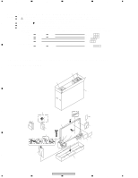
Parts List Mark No. Description Part No. > 1 Power Cord (2 m) 2 G-LINK Cable (3 m) 3 Remote Control Unit 4 Battery Cover NSP 5 Alkaline Dry Cell Battery (LR6, AA) ADG1215 VDX1010 AXD1531 AZN2681 VEM1023 6 Filter 7 Binder Assy 8 Cleaning Cloth 9 Operating Instructions D PRO-507PU 3 5 6 7 8 - Pioneer PRO-507PU | Service Manual - Page 4
Part No. PDP-5071PU KUCXC PRO-507PU KUCXC Remarks P23 - 1 PCB ASSEMBLIES 1..MAIN Assy AWV2312 AWV2309 P23 - 2 P23 - 3 P13 - 2 NSP 1..IO Assy 2..TANSHI ASSY 2..POD ASSY 2..SIDE ASSY AWV2313 AWW1156 AWW1154 AWW1157 AWV2310 AWW1153 AWW1158 AWW1155 1..HN MODULE Assy Not used AWV2311 - Pioneer PRO-507PU | Service Manual - Page 5
5 6 7 8 EXPLODED VIEWS A No.52 No.53 No.5 Note: see next page PMB30P080FNI No.51 POD Stay B AMZ30P060FTB No.54 B No.56 AMZ30P060FTB BMZ30P060FTB C BMZ30P060FTB D PRO-507PU 5 5 6 7 8 - Pioneer PRO-507PU | Service Manual - Page 6
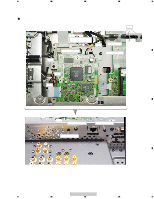
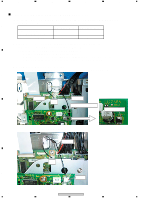
MAIN ass'y When AWV2311-B /J is used in the product, replace the defective ass'y with a service parts ass'y as shown in Figure B. B ADX3485 M17 ADX3483 Fix the wire by bond-lock. 4th pin in IC7803 C Figure A: AWV2311-A /J ADX3484 M17 D CN7802 Figure B: AWV2311-B /J 6 PRO-507PU 1 2 3 4 - Pioneer PRO-507PU | Service Manual - Page 7
R4901, R4902, R4904 Not used Not used CKSRYB105K10 RS1/16SS220J [MAIN UCOM BLOCK] R8454 R8470 R8469, R8453 RS1/16SS103J RS1/16SS103J Not used Not used Not used RS1/16SS103J Note: For Schematic Diagram and PCB Connection Diagram. Refer to "Service Manual: Order No. ARP3355" Remarks PRO-507PU - Pioneer PRO-507PU | Service Manual - Page 8
Part No. AWW1157 AWW1155 R9141 R9142 RS1/16SS0R0J Not used Not used RS1/16SS0R0J Remarks JA9101 AKB1303 AKB1304 C JA9102 AKB1305 AKB1306 Note: For Schematic Diagram and PCB Connection Diagram. Refer to "Service Manual: Order No. ARP3355" • HN MODULE ASSY (AWV2311 PRO-507PU 1 2 3 4 - Pioneer PRO-507PU | Service Manual - Page 9
C 7901 C 7902 C 7903,7906 C 7904 C 7905,7907,7908 C 7909 C 7910,7914,7917,7920 C 7911,7918 C 7912,7919 C 7913,7915,7916 PRO-507PU 6 7 Part No. LCTAWR47J2520 A ATX1066 ASS1211 CKS3888 RS1/16SS37R4F RS1/16SS75R0F RS1/16SS1501F RS1/16SS6801F RS1/16SS3301F RS1/16SS5101F RS1/16SS75R0F RS1/16SS - Pioneer PRO-507PU | Service Manual - Page 10
1 2 3 4 2. BLOCK DIAGRAM AND SCHEMATIC DIAGRAM 2.1 OVERALL WIRING DIAGRAM A B C D 10 1 AWV2313- (REGULAR) AWW1156 AWV2310- (ELITE) AWW1153 (REGULAR) AWV2313AWW1157 (ELITE) AWV2310AWW1155 PRO-507PU 2 3 4 - Pioneer PRO-507PU | Service Manual - Page 11
5 6 7 8 A (REGULAR) AWV2313- AWW1154 B (ELITE) AWV2310AWW1158 for AWV2311-A for AWV2311-B PRO-507PU 5 6 7 C D 11 8 - Pioneer PRO-507PU | Service Manual - Page 12
to outside of the ass'y xx MHz X'tal X'tal or oscillator Differential signal Host controll signal Power supply Bus signal Other digital signal USB block to USB Receptacle Connector CN7801 PCI IC] IC7904 LTC3412EFE [SW Reg. IC] IC7901 LM2664M6X [Converter IC] 12 PRO-507PU 1 2 3 4 - Pioneer PRO-507PU | Service Manual - Page 13
2 N.C. 3 GND 4 GND I/O description I +5V power supply - No use in this model - - MTB MAIN Ass'y [M15] CN4016 voltage (V) pin B +5.0 1 AWV2311-B. For AWV2311-A, a wire is directly soldered to 4th pin of IC78.03 MTB MAIN Ass'y CN4011 voltage (V) pin - 1 +5.1 2 - 3 D PRO-507PU - Pioneer PRO-507PU | Service Manual - Page 14
1 2 3 4 2.4 HN MODULE ASSY (1/6) HN MODULE ASSY (1/6) • 8620 BLOCK A Large size SCH diagram 1/2 B 2/2 1/2 C D 14 PRO-507PU 1 2 3 4 - Pioneer PRO-507PU | Service Manual - Page 15
5 6 7 8 A B C D PRO-507PU 15 5 6 7 8 - Pioneer PRO-507PU | Service Manual - Page 16
1 2 3 4 HN MODULE ASSY A (1/6) • 8620 BLOCK B Large size SCH diagram 1/2 C 2/2 2/2 D 16 PRO-507PU 1 2 3 4 - Pioneer PRO-507PU | Service Manual - Page 17
5 6 7 8 A B C D PRO-507PU 17 5 6 7 8 - Pioneer PRO-507PU | Service Manual - Page 18
1 2 3 4 2.5 HN MODULE ASSY (2/6) HN MODULE ASSY (2/6) • 86220 DDR BLOCK A B C D 18 PRO-507PU 1 2 3 4 - Pioneer PRO-507PU | Service Manual - Page 19
5 6 7 8 A B C D PRO-507PU 19 5 6 7 8 - Pioneer PRO-507PU | Service Manual - Page 20
1 2 3 4 2.6 HN MODULE ASSY (3/6) HN MODULE ASSY (3/6) • ETHERNET BLOCK A B C D 20 PRO-507PU 1 2 3 4 - Pioneer PRO-507PU | Service Manual - Page 21
5 6 7 8 A B C D PRO-507PU 21 5 6 7 8 - Pioneer PRO-507PU | Service Manual - Page 22
1 2 3 4 2.7 HN MODULE ASSY (4/6) HN MODULE ASSY (4/6) • HNM USB BLOCK A B C D 22 PRO-507PU 1 2 3 4 - Pioneer PRO-507PU | Service Manual - Page 23
5 6 7 8 A USB POWER SECTION B C D PRO-507PU 23 5 6 7 8 - Pioneer PRO-507PU | Service Manual - Page 24
1 2 3 4 2.8 HN MODULE ASSY (5/6) HN MODULE ASSY (5/6) • HNM IO BLOCK A B C D 24 PRO-507PU 1 2 3 4 - Pioneer PRO-507PU | Service Manual - Page 25
5 6 7 8 A B C D PRO-507PU 25 5 6 7 8 - Pioneer PRO-507PU | Service Manual - Page 26
1 2 3 4 2.9 HN MODULE ASSY (6/6) HN MODULE ASSY (6/6) • HNM POWER BLOCK A B C D 26 PRO-507PU 1 2 3 4 - Pioneer PRO-507PU | Service Manual - Page 27
5 6 7 8 A B C D For Power Sequence PRO-507PU 27 5 6 7 8 - Pioneer PRO-507PU | Service Manual - Page 28
. 4. View point of PCB diagrams. Connector Capacitor BCE Transistor B C EB C E SIDE A BCE Transistor with resistor DGS D G SD G S Field effect transistor P.C.Board Chip Part SIDE B Resistor array 3-terminal regulator • HN MODULE ASSY B 4 SIDE A C D 28 1 PRO-507PU 2 3 (ANP2148B) 4 - Pioneer PRO-507PU | Service Manual - Page 29
5 6 • HN MODULE ASSY 7 8 A SIDE B B C (ANP2148B) D PRO-507PU 29 5 6 7 8 - Pioneer PRO-507PU | Service Manual - Page 30
not support WMV. Below is the URL from which some WMV files of 720p resolution are available. http://www.microsoft.com/windows/window smedia/musicandvideo/hdvideo/contentsho wcase.aspx C IP Address: Make the same for the network address part designated by the Subnet mask. For the rest, use the - Pioneer PRO-507PU | Service Manual - Page 31
One of the supported video format is WMV. Below is the URL from which some WMV files of 720p resolution are available. http:// No Even if you use any USB device available, can't the symptom be improved? No The failed contents may be out of support. There may be something PRO-507PU 31 5 6 7 8 - Pioneer PRO-507PU | Service Manual - Page 32
Please wait for about 40 seconds until "Home Media Gallery" turns selectable. Check each wire connection with the MAIN ass'y. CN7901 and CN4016 has only three wires, though 4pin connector is used. No B Check the power supply for HNM ass'y. Check the parts around it. D 32 PRO-507PU 1 2 3 4 - Pioneer PRO-507PU | Service Manual - Page 33
5 6 7 5. IC INFORMATION • The information shown in the list is basic information and may not correspond exactly to that shown in the schematic diagrams. RTL8100CL-LF (HN MODULE Assy: IC7754) • Ethernet Controller IC Pin Arrangement 8 A B C D PRO-507PU 33 5 6 7 8 - Pioneer PRO-507PU | Service Manual - Page 34
1 2 3 4 Block Diagram A B C D 34 PRO-507PU 1 2 3 4 - Pioneer PRO-507PU | Service Manual - Page 35
5 6 7 8 A B C D PRO-507PU 35 5 6 7 8 - Pioneer PRO-507PU | Service Manual - Page 36
1 2 3 4 A B C D 36 PRO-507PU 1 2 3 4 - Pioneer PRO-507PU | Service Manual - Page 37
5 6 7 8 A B C D PRO-507PU 37 5 6 7 8 - Pioneer PRO-507PU | Service Manual - Page 38
1 2 3 4 A B C D 38 PRO-507PU 1 2 3 4 - Pioneer PRO-507PU | Service Manual - Page 39
5 6 7 8 A B C D PRO-507PU 39 5 6 7 8
-
 1
1 -
 2
2 -
 3
3 -
 4
4 -
 5
5 -
 6
6 -
 7
7 -
8
-
9
-
10
-
11
-
12
-
13
-
14
-
15
-
16
-
17
-
18
-
19
-
20
-
21
-
22
-
23
-
24
-
25
-
26
-
27
-
28
-
29
-
30
-
31
-
32
-
33
-
34
-
35
-
36
-
37
-
38
-
39
 |
 |
ORDER NO.
PIONEER CORPORATION
4-1, Meguro 1-chome, Meguro-ku, Tokyo 153-8654, Japan
PIONEER ELECTRONICS (USA) INC.
P.O. Box 1760, Long Beach, CA 90801-1760, U.S.A.
PIONEER EUROPE NV
Haven 1087, Keetberglaan 1, 9120 Melsele, Belgium
PIONEER ELECTRONICS ASIACENTRE PTE. LTD.
253 Alexandra Road, #04-01, Singapore 159936
PIONEER CORPORATION 2006
ARP3399
T – ZZY SEPT. 2006 Printed
in Japan
THIS MANUAL IS APPLICABLE TO THE FOLLOWING MODEL(S) AND TYPE(S).
Model
Type
Power Requirement
Remarks
PRO-507PU
KUCXC
AC120 V
PRO-507PU
PLASMA DISPLAY
This service manual should be used together with the following manual(s):
Model No.
Order No.
Remarks
PDP-5071PU/KUCXC
ARP3354
SAFETY INFORMATION,
EXPLODED VIEWS AND PARTS LIST, BLOCK DIAGRAM,
PCB PARTS LIST, ADJUSTMENT, IC INFORMATION etc.
ARP3355
SCHEMATIC DIAGRAM and PCB CONNECTION
DIAGRAM
CONTENTS
1. CONTRAST OF MISCELLANEOUS PARTS
..............................
2
2. BLOCK DIAGRAM AND SCHEMATIC DIAGRAM
...................
10
2.1 OVERALL WIRING DIAGRAM
............................................
10
2.2 HNM BLOCK DIAGRAM
.....................................................
12
2.3 CONNECTOR PIN DESCRIPTION
....................................
13
2.4 HN MODULE ASSY (1/6)
....................................................
14
2.5 HN MODULE ASSY (2/6)
....................................................
18
2.6 HN MODULE ASSY (3/6)
....................................................
20
2.7 HN MODULE ASSY (4/6)
....................................................
22
2.8 HN MODULE ASSY (5/6)
....................................................
24
2.9 HN MODULE ASSY (6/6)
....................................................
26
3. PCB CONNECTION DIAGRAM
................................................
28
3.1 HN MODULE ASSY
............................................................
28
4. TROUBLESHOOTING
..............................................................
30
5. IC INFORMATION
.....................................................................
33