Pioneer SC-55 Owner's Manual - Page 12
Connecting your equipment - setup
 |
View all Pioneer SC-55 manuals
Add to My Manuals
Save this manual to your list of manuals |
Page 12 highlights
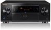
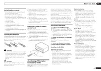
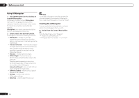
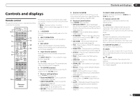
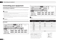
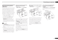
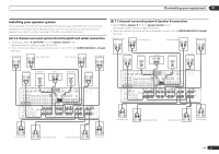
03 Connecting your equipment Connecting your equipment Connecting your equipment This receiver provides you with many connection possibilities, but it doesn't have to be difficult. This chapter explains the kinds of components you can connect to make up your home theater system. CAUTION ! Before making or changing the connections, switch off the power and disconnect the power cord from the power outlet. Plugging in should be the final step. ! When making connections, also keep the power cords of the devices being connected unplugged from the power outlets. ! Depending on the device being connected (amplifier, receiver, etc.), the methods of connection and terminal names may differ from the explanations in this manual. Also refer to the operating instructions of the respective devices. Important Illustration shows the SC-57, however connections for the SC-55 are the same except where noted. Rear panel SC-57 IN 1 IN 2 HDMI ASSIGNABLE 16 ASSIGNABLE Y COMPONENT VIDEO PB PR IN 1 (DVD) IN 4 (VIDEO) BD IN IN 5 (DVD) IN 6 (DVR/BDR) OUT 1 (CONTROL) OUT 2 DC OUTPUT for WIRELESS LAN (OUTPUT 5 V 0.6 A MAX) LAN (10/100) VIDEO SIRIUS COAXIAL ASSIGNABLE OPTICAL ASSIGNABLE MONITOR SIGNAL IN OUT GND IN 1 IN 2 IN 1 IN 2 IN 3 (DVD) (CD) (TV/SAT) (DVR/BDR) (VIDEO) ADAPTER PORT (OUTPUT 5 V 0.1 A MAX) OUT AC IN IN 2 (DVR/ BDR) IN 3 (VIDEO) MONITOR OUT ZONE 2 ZONE 3 DVD TV/SAT VIDEO OUT OUT IN IN IN DVR/BDR OUT IN PHONO IN CD IN FRONT 1 SUBWOOFER 2 SURROUND SURR BACK F HEIGHT (Single) F WIDE FRONT CENTER SURROUND SURR BACK L R ZONE2 OUT RS-232C A FRONT R AUDIO CENTER CENTER L FRONT HEIGHT R L PRE OUT FRONTWIDE / B R L SUBWOOFER MULTI CH IN SURROUND R L SURROUND BACK A R L (Single) AM LOOP ANTENNA FM UNBAL 75 IR IN 1 IN 1 SPEAKERS OUT IN 2 OUT 2 (OUTPUT 12 V (OUTPUT 5 V TOTAL 150 mA MAX) EXTENSION 150 mA MAX) CONTROL 12VTRIGGER 12 En SC-55 IN 1 IN 2 HDMI ASSIGNABLE 16 ASSIGNABLE Y COMPONENT VIDEO PB PR IN 1 (DVD) IN 4 (VIDEO) BD IN IN 5 (DVD) IN 6 (DVR/BDR) OUT 1 (CONTROL) OUT 2 DC OUTPUT for WIRELESS LAN (OUTPUT 5 V 0.6 A MAX) LAN (10/100) VIDEO SIRIUS COAXIAL ASSIGNABLE OPTICAL ASSIGNABLE MONITOR SIGNAL IN OUT GND IN 1 IN 2 IN 1 IN 2 IN 3 (DVD) (CD) (TV/SAT) (DVR/BDR) (VIDEO) ADAPTER PORT (OUTPUT 5 V 0.1 A MAX) OUT IN 2 (DVR/ BDR) IN 3 (VIDEO) MONITOR OUT ZONE 2 ZONE 3 DVD TV/SAT VIDEO OUT OUT IN IN IN DVR/BDR OUT IN PHONO IN CD IN FRONT 1 SUBWOOFER 2 SURROUND SURR BACK F HEIGHT (Single) F WIDE AC IN ZONE2 OUT RS-232C A FRONT R AUDIO CENTER CENTER L FRONT HEIGHT R L PRE OUT FRONTWIDE / B R L SURROUND R L SURROUND BACK A R L (Single) AM LOOP ANTENNA FM UNBAL 75 IR IN 1 IN 1 SPEAKERS OUT IN 2 OUT 2 (OUTPUT 12 V (OUTPUT 5 V TOTAL 150 mA MAX) EXTENSION 150 mA MAX) CONTROL 12VTRIGGER Note ! The input functions below are assigned by default to the receiver's different input terminals. Refer to The Input Setup menu on page 34 to change the assignments if other connections are used. Input function BD DVD TV/SAT DVR/BDR VIDEO HDMI 1 HDMI (BD) IN 5 IN 6 IN 4 IN 1 Input Terminals Digital Component COAX-1 IN 1 OPT-1 OPT-2 IN 2 OPT-3 IN 3 HDMI 2 HDMI 3 (front panel) CD IN 2 IN 3 COAX-2 ! The CU-RF100 omni-directional remote control (separately sold) can be connected to the RS-232C and EXTENSION terminals. Using the CU-RF100 lets you display the receiver's display information on the remote control display in your hands and operate it without worrying about obstacles or the direction in which the remote control is pointing. RS-232C AM LOOP ANTENNA IR FM UNBAL 75 IN 1 IN OUT IN 2 OUT (OUTPUT 5 V EXTENSION 150 mA MAX) CONTR
-
 1
1 -
2
-
3
-
4
-
5
-
6
-
 7
7 -
 8
8 -
 9
9 -
 10
10 -
 11
11 -
 12
12 -
 13
13 -
 14
14 -
 15
15 -
 16
16 -
 17
17 -
18
-
19
-
20
-
21
-
22
-
23
-
24
-
25
-
26
-
27
-
28
-
29
-
30
-
31
-
32
-
33
-
34
-
35
-
36
-
37
-
38
-
39
-
40
-
41
-
42
-
43
-
44
-
45
-
46
-
47
-
48
-
49
-
50
-
51
-
52
-
53
-
54
-
55
-
56
-
57
-
58
-
59
-
60
-
61
-
62
-
63
-
64
-
65
-
66
-
67
-
68
-
69
-
70
-
71
-
72
-
73
-
74
-
75
-
76
-
77
-
78
-
79
-
80
-
81
-
82
-
83
-
84
-
85
-
86
-
87
-
88
-
89
-
90
-
91
-
92
-
93
-
94
-
95
-
96
-
97
-
98
-
99
-
100
-
101
-
102
-
103
-
104
-
105
-
106
-
107
-
108
 |
 |