Pioneer VSX-70 Owner's Manual - Page 25
HDMI OUT 1, HDMI Setup
 |
View all Pioneer VSX-70 manuals
Add to My Manuals
Save this manual to your list of manuals |
Page 25 highlights
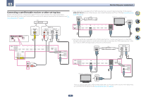
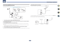
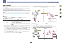
03 Connecting your equipment Connecting your DVD player with no HDMI output This diagram shows connections of a TV (with HDMI input) and DVD player (or other playback component with no HDMI output) to the receiver. HDMI/DVI-compatible monitor DVD player, etc. HDMI IN Select one VIDEO OUT VIDEO COMPONENT VIDEO OUT Y PB PR Select one AUDIO OUT DIGITAL OUT R ANALOG L OPTICAL COAXIAL Connecting your TV with no HDMI input This diagram shows connections of a TV (with no HDMI input) and DVD player (or other playback component) to the receiver. Important ! With these connections, the picture is not output to the TV even if the DVD player is connected with an HDMI cable. Connect the receiver and TV using the same type of video cable as used to connect the receiver and player. ! Also, when the receiver and TV are connected by anything other than an HDMI cable, the OSD function allowing display of the receiver's settings, operations, etc., on the TV's screen cannot be used. In this case, watch the receiver's front panel display while performing the various operations and making settings. DVD player, etc. TV HDMI OUT 2 (HDZONE) IN 1 BD IN IN 2 IN 3 IN 4 IN 6 IN 7 OUT 1 LAN (10/100) DC OUTPUT for WIRELESS LAN ASSIGNABLE 1-7 SELECTABLE (DVD) (SAT/CBL) (DVR/BDR) (CONTROL) (OUTPUT 5 V 0.6 A MAX) DVD IN OPTICAL IN 1 (TV) ASSIGNABLE COAXIAL IN 1 (DVD) ASSIGNABLE Select one COMPONENT VIDEO IN Y PB PR VIDEO IN VIDEO Select one COMPONENT VIDEO OUT Y PB PR VIDEO OUT VIDEO HDMI OUT Select one DIGITAL OUT COAXIAL OPTICAL AUDIO OUT R ANALOG L IN 1 (DVD) ASSIGNABLE IN 2 (DVR/ BDR) MONITOR OUT Y PB PR DVD COMPONENT VIDEO HDMI OUT 2 (HDZONE) IN 1 BD IN IN 2 IN 3 IN 4 IN 6 IN 7 OUT 1 LAN (10/100) DC OUTPUT for WIRELESS LAN ASSIGNABLE 1-7 SELECTABLE (DVD) (SAT/CBL) (DVR/BDR) (CONTROL) (OUTPUT 5 V 0.6 A MAX) DVD IN IN 1 (DVD) ASSIGNABLE IN 2 (DVR/ BDR) MONITOR OUT Y PB PR DVD COMPONENT VIDEO OPTICAL IN 1 (TV) ASSIGNABLE COAXIAL IN 1 (DVD) ASSIGNABLE ! If you want to listen to the sound of the TV over the receiver, connect the receiver and TV with audio cables (page 24). - When the TV and receiver are connected by HDMI connections, if the TV supports the HDMI ARC (Audio Return Channel) function, the sound of the TV can be input to the receiver via the HDMI OUT 1 terminal, so there is no need to connect an audio cable. In this case, set ARC at HDMI Setup to ON (see HDMI Setup on page 59). ! If you use an optical digital audio cable or RCA (analog) audio cable, you'll need to tell the receiver which digital input you connected the player to (see The Input Setup menu on page 37). HDMI OUT 2 (HDZONE) IN 1 BD IN IN 2 IN 3 IN 4 ASSIGNABLE 1-7 SELECTABLE (DVD) VIDEO MONITOR ZONE 2 OUT OUT SAT/CBL IN DVR/BDR IN DVD IN IN 1 (DVD) ASSIGNABLE IN 2 (DVR/ BDR) (SAT/CBL) (DVR/BDR) MONITOR OUT Y PB PR DVD COMPONENT VIDEO IN 6 IN 7 OUT 1 LAN (10/100) DC OUTPUT for WIRELESS LAN (CONTROL) (OUTPUT 5 V 0.6 A MAX) OPTICAL IN 1 (TV) ASSIGNABLE COAXIAL IN 1 (DVD) ASSIGNABLE HDMI OUT 2 (HDZONE) IN 1 BD IN IN 2 IN 3 IN 4 IN 6 IN 7 OUT 1 LAN (10/100) DC OUTPUT for WIRELESS LAN ASSIGNABLE 1-7 SELECTABLE (DVD) VIDEO (SAT/CBL) (DVR/BDR) (CONTROL) (OUTPUT 5 V 0.6 A MAX) MONITOR ZONE 2 OUT OUT SAT/CBL IN DVR/BDR IN DVD IN IN 1 (DVD) ASSIGNABLE IN 2 (DVR/ BDR) MONITOR OUT Y PB PR DVD COMPONENT VIDEO OPTICAL IN 1 (TV) ASSIGNABLE COAXIAL IN 1 (DVD) ASSIGNABLE 25
-
 1
1 -
2
-
3
-
4
-
5
-
6
-
7
-
8
-
9
-
10
-
11
-
12
-
13
-
14
-
15
-
16
-
17
-
18
-
19
-
 20
20 -
 21
21 -
 22
22 -
 23
23 -
 24
24 -
 25
25 -
 26
26 -
 27
27 -
 28
28 -
 29
29 -
 30
30 -
31
-
32
-
33
-
34
-
35
-
36
-
37
-
38
-
39
-
40
-
41
-
42
-
43
-
44
-
45
-
46
-
47
-
48
-
49
-
50
-
51
-
52
-
53
-
54
-
55
-
56
-
57
-
58
-
59
-
60
-
61
-
62
-
63
-
64
-
65
-
66
-
67
-
68
-
69
-
70
-
71
-
72
-
73
-
74
-
75
-
76
-
77
-
78
-
79
-
80
-
81
-
82
-
83
-
84
-
85
-
86
-
87
-
88
-
89
-
90
-
91
-
92
-
93
-
94
-
95
-
96
-
97
-
98
-
99
-
100
-
101
-
102
-
103
-
104
-
105
-
106
-
107
-
108
-
109
-
110
-
111
-
112
-
113
-
114
 |
 |
