Poulan 1980-06 User Manual - Page 8
rezeio°, CHAIN, TENSION
 |
View all Poulan 1980-06 manuals
Add to My Manuals
Save this manual to your list of manuals |
Page 8 highlights
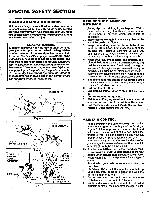
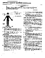
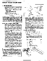
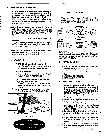
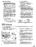
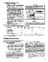
2. Mount the Guide Bar with the slotted end over the bar mounting studs. Figure 9 . NOTE Be sure the Guide Bar is positioned with the round hole below the large slot. 3. Hold chain with cutters facing as shown in Figure 10. 4. Place chain over and behind the dutch drum onto the sprocket. 5. Slide Guide Bar to the rear of the saw as far as possible. 6. Fit the bottom of the drive links between the teeth in the sprocket. 7. Start at the top of the bar and fit the chain drive links into the groove around the Guide Bar. Figure 10. 8. Pull the Guide Bar forward until the chain is snug in the guide bar groove. Figure 11. 9. Install the outer guide plate. Figure 7. 10. SlidetheBarClampoverthemountingstudsandfit the baradjustingpin(Figure11)intotheadjustingpin hole in the Guide Bar. Figure 9. 11. Replace the Bar Mounting Nuts and tighten finger tight only. NOTE: The Bar Clamp nuts must be slightly loose to tension the chain correctly. 12. Follow "Chain Tension" instructions below. D. CHAIN TENSION • Correct chain tension is very important: -a loose chain will wear the bar and itself. -a loose chain can jump off the bar while you are cutting. -a tight chain can damage the saw and/or break. • Chain tension is correct when the chain: - can be lifted about 1/8" from the Guide Bar at a point near the middle of the bar, and -will move freely around the bar. -• The chain stretches during use, especially when new.Check tension: - each time the saw is used - more frequently when the chain is new - as the chain warms up to normal operating temperature 1. Hold the tip of the Guide Bar up and turn the Adjusting Screw just until the chain does not sag beneath the Guide Bar.Figure 12. NOTE: Turn screw clockwise to tighten tension. Turn screw counterclockwise to loosen tension. 2. Check the tension by lifting the chain from the Guide Bar at the center of the bar. Figure 13. 3. Continue turning the Adjusting Screw until the tension is correct. 4. Hold the tip of the Guide Bar up and tighten the Bar Clamp Nuts with the Scrench. 5. Recheck tension. CLUTCH BAR MOUNTING STUDS ADJUSTING • PIN HOLE PM • - Figure 9 GUIDE BAR Chain Travel Cutters Op Drive Links of ?rezeio° Figure 10 BAR ADJUSTING PIN PI 6 6 Figure 11 0 BAR MOUNTING STUDS ADJUSTING SCREW Figure 12 CHAIN CAN BE LIFTED1/8"WHEN TENSION IS CORRECT. 1/8" TURN Aase TO LOOSEN TENSION TURN •••-l\ TO TIGHTEN TENSION 0 Figure 13
-
 1
1 -
2
-
 3
3 -
 4
4 -
 5
5 -
 6
6 -
 7
7 -
 8
8 -
 9
9 -
 10
10 -
 11
11 -
 12
12 -
 13
13 -
14
-
15
-
16
-
17
-
18
-
19
-
20
-
21
-
22
-
23
-
24
-
25
-
26
-
27
-
28
 |
 |
