Poulan 220LE User Manual - Page 5
Assembly - parts
 |
View all Poulan 220LE manuals
Add to My Manuals
Save this manual to your list of manuals |
Page 5 highlights
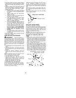
and bar as original equipment. Repairs on a chain brake should be made by an autho- rized servicing dealer. Take your unit to the place of purchase if purchased from a servicing dealer, or to the nearest authorized master service dealer. ASSEMBLY Protective gloves (not provided) should be worn during assembly. S Tip contact in some cases may cause a lightning fast reverse REACTION, kicking the guide bar up and back toward the operator. S Pinching the saw chain along the top of the guide bar may push the guide bar rapidly back toward the operator. S Either of these reactions may cause you to lose control of the saw which could result in serious injury.Do not rely exclusively upon the safety devices built into your saw. NOTE: If this saw is to be used for commercial logging, a chain brake is required and shall not be removed or otherwise disabled to comply with Federal OSHA Regulations for Commercial Logging. Contact your Authorized Service Dealer or call 1--800--554--6423. ATTACHING THE BAR & CHAIN (If not already attached) WARNING: If received assembled, repeat all steps to ensure your saw is properly assembled and all fasteners are secure. Always wear gloves when handling the chain. The chain is sharp and can cut you even when it is not moving! S Loosen and remove the chain brake nuts and the chain brake from the saw. S Remove the plastic shipping spacer (if present). Location of shipping spacer SAFETY NOTICE: Exposure to vibrations through prolonged use of gasoline powered hand tools could cause blood vessel or nerve damage in the fingers, hands, and joints of people prone to circulation disorders or abnormal swellings. Prolonged use in cold weather has been linked to blood vessel damage in otherwise healthy people. If symptoms occur such as numbness, pain, loss of strength, change in skin color or texture, or loss of feeling in the fingers, hands, or joints, discontinue the use of this tool and seek medical attention. An anti-vibration system does not guarantee the avoidance of these problems. Users who operate power tools on a continual and regular basis must monitor closely their physical condition and the condition of this tool. SPECIAL NOTICE: Your saw is equipped Chain Brake Chain Brake Nuts Bar Tool S Turn adjusting screw on bar counterclockwise to move the tensioning rack as far as it will go toward the front of the bar. Adjusting Screw with a temperature limiting muffler and spark arresting screen which meets the requirements of California Codes 4442 and 4443. All U.S. forest land and the states of California, Idaho, Maine, Minnesota, New Jersey, Oregon, and Washington require by law that many internal combustion engines to be equipped with a spark arresting screen. If you operate a chain saw in a state or locale where such regulations exist, you are legally responsible for maintaining the operating condition of these parts. Failure to do so is a violation of the law. Refer to the SERVICE section for maintenance of the spark arresting screen. STANDARDS: This saw is listed by Underwriter's Laboratories, Inc., in accordance with American National Standards for Gasoline--Powered Chain Saw Safety Requirements (ANSI B175.1-1991). Failure to follow all Safety Rules and Precautions can result in serious injury. If situations occur which are not covered in this manual, Tensioning Rack S Mount the bar as illustrated. S Slide the bar behind clutch drum until bar stops against clutch drum sprocket. S Prepare the chain by checking the proper direction. Without following the illustration it is easy to place the chain on the saw in the wrong direction. Use the illustration of the chain to determine the proper direction. S Place the chain onto the sprocket located behind the clutch drum (see illustration). Fit the chain between the teeth in the sprocket. S Start at the top of the bar and fit chain into groove around the guide bar. S Pull the bar forward until the chain is snug in the groove of the bar. Ensure all drive use care and good judgement. If you need assistance, contact your Authorized Service Dealer or call 1-800--554--6723. links are in the bar groove. S Hold guide bar against the saw frame and install the chain brake. 5
-
 1
1 -
 2
2 -
 3
3 -
 4
4 -
 5
5 -
 6
6 -
 7
7 -
 8
8 -
 9
9 -
 10
10 -
 11
11 -
12
-
13
-
14
-
15
-
16
 |
 |
