Poulan PB22H54BF User Manual - Page 8
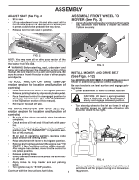
tractor. Insert rod end of link assembly through
 |
View all Poulan PB22H54BF manuals
Add to My Manuals
Save this manual to your list of manuals |
Page 8 highlights
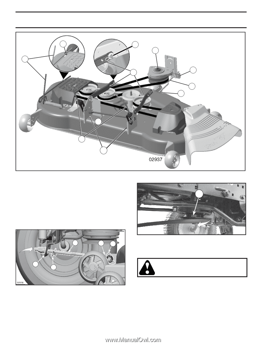
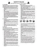
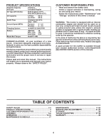
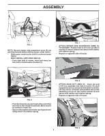
L K ASSEMBLY B M A F E H S C D FIG. 10 • Turn steering wheel to position wheels straight forward. • ATTACH FRONT LINK (E) - Work from left side of tractor. Insert rod end of link assembly through M front hole in tractor front suspension bracket (F) and secure with7/16 retainer spring (G) through hole in link located behind the bracket. • Insert other end of link (E) into hole in front mower bracket (H) and secure with washer and 5/16 retainer spring (J). E H J FIG. 12 • Engage belt tension rod (K) on locking bracket (L). F G CAUTION: Belt tension rod is spring loaded. Have a tight grip on rod and engage slowly. • FIG. 11 • • Disengage belt tension rod (K) from locking bracket (L). • Install belt onto engine clutch pulley (M). IMPORTANT: Check belt for proper routing in all mower pulley grooves. 8 Raise attachment lift lever to highest position. If necessary, adjust gauge wheels before operating mower as shown in the Operation section of this manual.
-
 1
1 -
2
-
 3
3 -
 4
4 -
 5
5 -
 6
6 -
 7
7 -
 8
8 -
 9
9 -
 10
10 -
 11
11 -
 12
12 -
 13
13 -
14
-
15
-
16
-
17
-
18
-
19
-
20
-
21
-
22
-
23
-
24
-
25
-
26
-
27
-
28
-
29
-
30
-
31
-
32
-
33
-
34
-
35
-
36
-
37
-
38
-
39
-
40
-
41
-
42
-
43
-
44
-
45
-
46
-
47
-
48
-
49
-
50
-
51
-
52
-
53
-
54
-
55
-
56
-
57
-
58
-
59
-
60
-
61
-
62
-
63
-
64
 |
 |