Poulan PO1538D User Manual - Page 21
To Ad, Just Steer, Ing Wheel Align, Front Wheel Toe-in/camber, To Replace Motion Drive Belt, See Fig
 |
View all Poulan PO1538D manuals
Add to My Manuals
Save this manual to your list of manuals |
Page 21 highlights
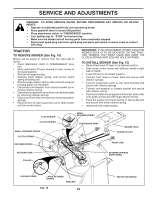
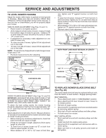
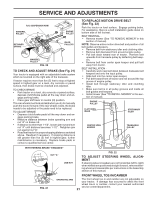
SERVICE AND ADJUSTMENTS R.H. SUSPENSION ARM MANDREL PULLEY 38 42 RETAINER SPRING ENGINE PULLEY IDLER PULLEYS MANDREL PULLEY FIG. 20 TO CHECK AND ADJUST BRAKE (See Fig. 21) Your tractor is equipped with an adjustable brake system which is mounted on the right side of the transaxle. If tractor requires more than five (5) feet to stop at highest speed in highest gear on a level, dry concrete or paved surface, then brake must be checked and adjusted. TO CHECK BRAKE • Park tractor on a level, dry concrete or paved surface, depress clutch/brake pedal all the way down and engage parking brake. • Place gear shift lever in neutral (N) position. The rear wheels must lock and skid when you try to manually push the tractor forward. If the rear wheels rotate, the brake needs to be adjusted or the pads need to be replaced. TO ADJUST BRAKE • Depress clutch/brake pedal all the way down and en- gage parking brake. • Measure distance between brake operating arm and nut "A" on brake rod. • If distance is other than 1-1/2", loosen jam nut and turn nut "A" until distance becomes 1-1/2". Retighten jam nut against nut "A". • Road test tractor for proper stopping distance as stated above. Readjust if necessary. If stopping distance is still greater than five (5) feet in highest gear, further maintenance is necessary. Replace brake pads or contact a qualified service center. TO REPLACE MOTION DRIVE BELT (See Fig. 22) Park the tractor on level surface. Engage parking brake. For assistance, there is a belt installation guide decal on bottom side of left footrest. BELT REMOVAL • Remove mower (See "TO REMOVE MOWER" in this section of manual). NOTE: Observe entire motion drive belt and position of all belt guides and keepers. • Remove belt from stationary idler and clutching idler. • Remove belt downward from around engine pulley. • Pull belt slack toward rear of tractor. Remove belt upwards from transaxle pulley by deflecting belt keepers. • Remove belt from center span keeper and pull belt away from tractor. BELT INSTALLATION • Carefully work new belt down between transaxle belt keepers and onto the input pulley. • Slide belt into the center span keeper. • Pull belt toward front of tractor and roll around the top groove of engine pulley. • Install belt through stationary idler and clutching idler. • Make sure belt is in all pulley grooves and inside all belt guides and keepers. • Install mower (See "TO INSTALL MOWER" in this sec- tion of manual). ENGINE PULLEY CLUTCHING IDLER STATIONARY IDLER CENTER SPAN KEEPER TRANSAXLE PULLEY WITH PARKING BRAKE "ENGAGED" 1-1/2" NUT "A" JAM NUT FIG. 21 OPERATING ARM FIG. 22 TO ADJUST STEERING WHEEL ALIGNMENT If steering wheel crossbars are not horizontal (left to right) when wheels are positioned straight forward, remove steering wheel and reassemble per instructions in the Assembly section of this manual. FRONT WHEEL TOE-IN/CAMBER The front wheel toe-in and camber are not adjustable on your tractor. If damage has occurred to affect the front wheel toe-in or camber, contact your nearest authorized service center/department. 21
-
 1
1 -
2
-
3
-
4
-
5
-
6
-
7
-
8
-
9
-
10
-
11
-
12
-
13
-
14
-
15
-
 16
16 -
 17
17 -
 18
18 -
 19
19 -
 20
20 -
 21
21 -
 22
22 -
 23
23 -
 24
24 -
 25
25 -
 26
26 -
27
-
28
-
29
-
30
-
31
-
32
-
33
-
34
-
35
-
36
-
37
-
38
-
39
-
40
-
41
-
42
-
43
-
44
 |
 |
