Poulan PP291EPS30 User Manual
Poulan PP291EPS30 Manual
 |
View all Poulan PP291EPS30 manuals
Add to My Manuals
Save this manual to your list of manuals |
Poulan PP291EPS30 manual content summary:
- Poulan PP291EPS30 | User Manual - Page 1
IMPORTANT MANUAL Do Not Throw Away OWNER'S MANUAL MODEL NUMBER: PP291EPS30 SNOW THROWER WARNING: Read the Owner's Manual and follow all Warnings and Safety Instructions. Failure to do so can result in serious injury. Always Wear Eye Protection During Operation 440642 11.08.10 TH Printed in - Poulan PP291EPS30 | User Manual - Page 2
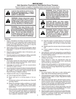
startup. CAUTION: Muffler and other engine parts become extremely hot during operation and remain understand and follow all instructions on the machine and in the manual(s) before operating this powered equipment Vibration is generally a warning of trouble. from the truck or trailer and refuel - Poulan PP291EPS30 | User Manual - Page 3
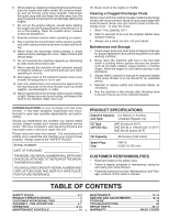
moving parts instructions under "Maintenance" and "Storage" sections of this owner's manual. TABLE OF CONTENTS SAFETY RULES 2-3 MAINTENANCE 14-15 PRODUCT SPECIFICATIONS 3 SERVICE AND ADJUSTMENTS 16-18 CUSTOMER RESPONSIBILITIES 3 STORAGE 19 ASSEMBLY / PRE-OPERATION 5-7 TROUBLESHOOTING - Poulan PP291EPS30 | User Manual - Page 4
PARTS PACKED SEPARATELY IN CARTON (1) POWER CORD (198563) (1) MULTIWRENCH (180684) (3) RETAINER SPRINGS (169675) (2) FLAT WASHERS (2) SHEAR BOLTS 1/4-20 x 1-3/4 (192090) (2) LOCKNUTS 1/4-20 (73800400) (2) CARRIAGE BOLTS 3/8-16 x 2.25 (2) - Poulan PP291EPS30 | User Manual - Page 5
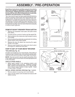
these instructions and this manual in its entirety before you attempt to assemble or operate your new snow thrower. Reading the entire manual will familiarize cover. Store the extra shear bolts, nuts and multi-wrench provided in parts bag in the toolbox. NOTE: The multi-wrench may be used for - Poulan PP291EPS30 | User Manual - Page 6
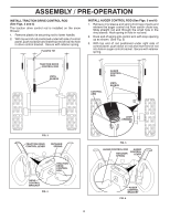
control bracket. Secure with retainer spring. PLASTIC TIE INSTALL AUGER CONTROL ROD (See Figs. 5 and 6) 1. Retrieve vinyl sleeve and spring from bag of parts and retrieve the auger control rod from carton chute tray. Slide straight rod end through the small hole in the vinyl sleeve. Hook spring in - Poulan PP291EPS30 | User Manual - Page 7
ASSEMBLY / PRE-OPERATION INSTALL DISCHARGE CHUTE / CHUTE ROTATOR HEAD (See Fig. 7) NOTE: The multi-wrench provided in your parts bag may be used to install the chute rotator head. 1. Place discharge chute assembly on top of chute base with discharge opening toward front of - Poulan PP291EPS30 | User Manual - Page 8
yourself with the location of various controls and adjustments. Save this manual for future reference. These symbols may appear on your snow READ AND FOLLOW ALL SAFETY INFORMATION AND INSTRUCTIONS BEFORE USE OF THIS PRODUCT. KEEP THESE INSTRUCTIONS FOR FUTURE REFERENCE. IGNITION KEY. INSERT - Poulan PP291EPS30 | User Manual - Page 9
MUFFLER GASOLINE FILLER CAP CHOKE CONTROL SAFETY IGNITION KEY ON / OFF SWITCH PRIMER FUEL SHUT-OFF VALVE RECOIL (AUXILIARY) STARTER HANDLE OPERATION ELECTRIC AUGER DISCHARGE CHUTE CONTROL LEVER START CONTROL BUTTON LEVER DRIVE SPEED CONTROL LEVER DEFLECTOR REMOTE CONTROL LEVER POWER CORD - Poulan PP291EPS30 | User Manual - Page 10
CONTROL SNOW DISCHARGE (See Fig. 13) WARNING: Snow throwers have exposed rotating parts, which can cause severe injury from contact, or from material thrown from chute or auger become clogged, shut-off engine and wait for all moving parts to stop. Use the clean-out tool, NOT YOUR HANDS, to unclog - Poulan PP291EPS30 | User Manual - Page 11
. 17 SPEED and DIRECTION are controlled by the drive speed TO ADJUST SKID PLATES (See Fig. 17) control lever. NOTE: The wrench provided in your parts bag may be • Press downward on the speed control lever and move used to adjust the skid plates. lever to desired position BEFORE engaging the - Poulan PP291EPS30 | User Manual - Page 12
wait for all moving parts to stop. 2. Adjust reversed, providing additional service before requiring replacement. Replace in the Maintenance section of this manual. ADD GASOLINE (See Fig. 19) . To avoid engine problems, the fuel system season. See Storage Instructions for additional information. - Poulan PP291EPS30 | User Manual - Page 13
position. COLD START - RECOIL STARTER 1. Insert safety ignition key (packed separately in parts bag) into ignition slot until it clicks. DO NOT turn the key. Keep conditions. See "TO ADJUST SKID PLATES" in this section of this manual. • For extremely heavy snow, reduce the width of snow removal by - Poulan PP291EPS30 | User Manual - Page 14
instructed in this manual. Some adjustments will need to be made periodically to properly maintain your snow thrower. All adjustments in the Service and Adjustments section of this manual schedule in this manual. NOTE: Use only Original Equipment Manufacturer (OEM) parts to service this unit. Failure - Poulan PP291EPS30 | User Manual - Page 15
(if removed for draining oil). Be sure to install klik pin into proper hole in wheel axle (See "TO REMOVE WHEELS" in the Service and Adjustments section of this manual). 7. Remove oil fill cap/dipstick. Be careful not to allow dirt to enter the engine. 8. Refill engine with oil through oil dipstick - Poulan PP291EPS30 | User Manual - Page 16
service or adjustments: 1. Be sure the on/off switch is in the OFF position. 2. Remove safety ignition key. 3. Make sure the augers and all moving parts discharged, see "TO CONTROL SNOW DISCHARGE" in the Operation section of this manual. SHEAR BOLTS (See Fig. 21) AUGER SHEAR BOLTS Both right and left - Poulan PP291EPS30 | User Manual - Page 17
should be replaced. It is recommended that the belt(s) be replaced by a service center/department. NOTE: It is recommended that both the auger and traction drive COVER - See "TO REMOVE BELT COVER" in this section of this manual. 4. REMOVE ENGINE PULLEY - Remove bolt, flat washer securing pulley to - Poulan PP291EPS30 | User Manual - Page 18
). Inner hole in axle and hole in wheel hub are not used for your model snow thrower. NOTE: To seal punctures or prevent flat tires due to slow leaks, tire sealant may be purchased from your local parts dealer. Tire sealant also prevents tire dry rot and corrosion. KLIK PIN (INSTALL IN OUTER - Poulan PP291EPS30 | User Manual - Page 19
Service and Adjustments section of this manual). 3. Lubricate as shown in the Maintenance section of this manual. 4. Be sure that all nuts, bolts, screws, and pins are securely fastened. Inspect moving parts and/or dirt in your gasoline will cause problems. • If possible, store your snow thrower - Poulan PP291EPS30 | User Manual - Page 20
TROUBLESHOOTING See appropriate section in manual unless directed to an authorized service center/department. PROBLEM CAUSE CORRECTION ON position). 5. Move to FULL position. 6. Prime as instructed in the Operation section of this manual. 7. Wait a few minutes before restarting, DO NOT prime. - Poulan PP291EPS30 | User Manual - Page 21
SERVICE NOTES 21 - Poulan PP291EPS30 | User Manual - Page 22
REPAIR PARTS SNOW THROWER - MODEL PP291EPS30 (96198004100) AUGER HOUSING / IMPELLER ASSEMBLY 5 15 14 4 11 6 11 16 12 = 25.4 mm IMPORTANT: Use only Original Equipment Manufacturer (O.E.M.) replacement parts. Failure to do so could be hazardous, damage your snow thrower and void your warranty. - Poulan PP291EPS30 | User Manual - Page 23
REPAIR PARTS SNOW THROWER - MODEL PP291EPS30 (96198004100) AUGER HOUSING / IMPELLER ASSEMBLY KEY NO. 1 2 3 4 5 6 7 8 9 10 11 12 13 14 15 16 17 18 19 20 21 22 23 24 25 26 27 28 29 30 31 32 33 34 35 36 37 PART NO. 175321X431 427148 188909 427146 175322 178675X431 192199 405400 73800400 74780426 - Poulan PP291EPS30 | User Manual - Page 24
REPAIR PARTS SNOW THROWER - MODEL PP291EPS30 (96198004100) AUGER HOUSING / IMPELLER ASSEMBLY 1 3 (5x) 4 (5x) 2 01.07.003-A KEY NO. 1 2 3 4 PART NO. 404930X428 404933X431 72270505 155377 DESCRIPTION AUGER HOUSING SCRAPPER BAR CARRIAGE BOLT 5/16−18 X .625 NUT 5/16−18 2 3 1 1 2 KEY PART NO. - Poulan PP291EPS30 | User Manual - Page 25
REPAIR PARTS SNOW THROWER - MODEL PP291EPS30 (96198004100) AUGER HOUSING / IMPELLER ASSEMBLY 2 1 KEY PART NO. NO. DESCRIPTION 1 420497X431 AUGER ASSEMBLY 30 LH 2 420498X431 AUGER ASSEMBLY 30 RH 01.07.019-A 4 3 2 3 4 1 01.11.001-B KEY NO. 1 2 3 4 PART NO. 174762X431 178777X431 - Poulan PP291EPS30 | User Manual - Page 26
REPAIR PARTS SNOW THROWER - MODEL PP291EPS30 (96198004100) AUGER HOUSING / IMPELLER ASSEMBLY 2 1 3 4 2 5 01.16.001-B 5 4 3 1 KEY NO. 1 2 3 4 5 PART NO. 181160X431 72270506 179246 10040500 128638 DESCRIPTION DRIFT CUTTER BAR CARRIAGE BOLT 5/16−18 X .750 PLASTIC WASHER LOCKWASHER 5/16 NUT 5/ - Poulan PP291EPS30 | User Manual - Page 27
PARTS SNOW THROWER - MODEL PP291EPS30 (96198004100) CONTROL PANEL / DISCHARGE CHUTE 5 7 15 3 16 *14 *11 2 4 6 *10 KEY NO. 1 2 3 4 5 6 7 8 9 *10 *11 *12 *13 *14 15 16 PART X .625 NUT 5/16-18 DEFLECTOR SPRING (SERVICE PART) DEFLECTOR CONTROL (SERVICE PART) DEFLECTOR CABLE BLACK *13 *12 9 8 - Poulan PP291EPS30 | User Manual - Page 28
PARTS SNOW THROWER - MODEL PP291EPS30 (96198004100) CONTROL PANEL / DISCHARGE CHUTE 2 2 *3 1 *7 *6 KEY NO. 1 2 *3 *4 *5 *6 *7 PART NO NOTES: 1. ITEMS INDICATED WITH AN * ARE LISTED AS REFERENCE FOR SERVICE PARTS ONLY. 2 KEY PART NO. NO. DESCRIPTION 1 01.15.009-A 1 421249 STEER CABLE - Poulan PP291EPS30 | User Manual - Page 29
REPAIR PARTS HANDLES SNOW THROWER - MODEL PP291EPS30 (96198004100) 3 7 2 5 6 4 5 1 4 01.10.006-B KEY NO. 1 2 3 4 5 6 7 PART NO. 182906 178668 178666 184471 175262 180964 401620 DESCRIPTION PANEL CONSOLE HEADLIGHT BEZEL HALOGEN HEADLIGHT SHOULDER SCREW SCREW 10−24 X 1.25 WIRE HARNESS BULB 4 5 - Poulan PP291EPS30 | User Manual - Page 30
HANDLES SNOW THROWER - MODEL PP291EPS30 (96198004100) 4 4 3 2 01.08.004-B 3 4 4 3 3 KEY PART NO. NO. DESCRIPTION 1 2 13 4 419798X431 419799X431 74780524 751153 LOOP HANDLE LH LOOP HANDLE RH SCREW 5/16−18 X 1.50 NUT 5/16−18 1 2 4 3 KEY NO. 1 2 3 4 PART NO. 419797X431 427513X431 428867 - Poulan PP291EPS30 | User Manual - Page 31
HANDLES SNOW THROWER - MODEL PP291EPS30 (96198004100) 10 2 11 9 5 7 6 8 47 9 1 3 13 8 13 14 12 12 14 01.08.002-G KEY NO. 1 2 3 4 5 6 7 8 9 10 11 12 13 14 PART NO. 412683X431 424517X431 424516X431 412679X008 426918X008 412677 421613 169675 17060410 414280 414281 178899 19131316 72120618 - Poulan PP291EPS30 | User Manual - Page 32
REPAIR PARTS HANDLES SNOW THROWER - MODEL PP291EPS30 (96198004100) 2 10 10 1 3 8 9 4 KEY NO. 1 2 3 4 5 6 7 8 9 10 PART NO. 180480 405740 180445 187716 180447 178669 180926 72270505 155377 169675 DESCRIPTION IMPELLER ROD ASSEMBLY TRACTION ROD ASSEMBLY SHIFTER ROD TOP SHIFTER ROD BOTTOM SPRING - Poulan PP291EPS30 | User Manual - Page 33
DRIVE SNOW THROWER - MODEL PP291EPS30 (96198004100) 6 7 1b 8 4 3 1b 7 1a 5 6 2 3 4 01.03.002-A KEY NO. 1 1a 1b 2 3 4 5 6 7 8 PART NO. 404923 404307 184206 402691 174697 179830 146315 17490508 155443 189282 DESCRIPTION AXLE ASSEMBLY (assy of 1a,1b) AXLE SHAFT ROLL PIN 3/16 X 1.50 SPROCKET - Poulan PP291EPS30 | User Manual - Page 34
REPAIR PARTS DRIVE SNOW THROWER - MODEL PP291EPS30 (96198004100) 42 EXPLODED 2 16 1 17 15 14 15 12 9 11 11 20 = 25.4 mm IMPORTANT: Use only Original Equipment Manufacturer (O.E.M.) replacement parts. Failure to do so could be hazardous, damage your snow thrower and void your warranty. 34 - Poulan PP291EPS30 | User Manual - Page 35
DRIVE SNOW THROWER - MODEL PP291EPS30 (96198004100) KEY NO. 1 2 3 4 5 6 7 8 9 10 11 12 13 14 15 16 17 18 19 20 21 22 23 24 25 26 PART NO. 198875 17501010 402685X428 17490508 57079 405485 198580 403097X008 402881 403096X431 191730 402856X008 416717X431 187101 700279 427542 402568 169675 401732 - Poulan PP291EPS30 | User Manual - Page 36
REPAIR PARTS SNOW THROWER - MODEL PP291EPS30 (96198004100) CHASSIS / ENGINE / PULLEYS 2 3 2 3 1 01.00.034-A KEY NO. - 1 2 3 PART NO. 436263 418694X428 150406 428867 DESCRIPTION COMPLETE LCT ENGINE FRAME BOLT 3/8-16 SCREW 5/16-18 X .750 1 01.01.004-A 1 KEY NO. 1 PART NO. 427963X428 - Poulan PP291EPS30 | User Manual - Page 37
PARTS SNOW THROWER - MODEL PP291EPS30 (96198004100) CHASSIS / ENGINE / PULLEYS 25 24 27 23 22 13 21 20 15 11 12 13 21 26 13 14 7 19 18 17 16 5 9 4 6 3 1 10 2 8 KEY NO. 1 2 3 4 5 6 7 8 9 10 11 12 13 14 PART X 1.00 LOCKWASHER 5/16 BELT GUIDE LOCKWASHER 5/16 IDLER BUSHING WASHER SCREW - Poulan PP291EPS30 | User Manual - Page 38
WHEELS SNOW THROWER - MODEL PP291EPS30 (96198004100) 2 2 17 23 43 1 20 19 16 17 18 15 22 16 24 65 7 98 10 20 23 21 11 22 19 21 12 14 11 10 9 1214 13 13 8 2 7 6 5 34 KEY PART NO. NO. DESCRIPTION 1 2 01.15.001-B 1 405161 COVER 2 184471 SHOULDER SCREW 3 12000045 - Poulan PP291EPS30 | User Manual - Page 39
WHEELS SNOW THROWER - MODEL PP291EPS30 (96198004100) KEY PART NO. NO. DESCRIPTION 1 432340X421 WHEEL ASSEMBLY LH 2 432341X421 WHEEL ASSEMBLY RH 1 2 01.06.014-A 1 2 01.15.003-C KEY PART NO. NO. 1 410293 2 4 33 4 410294 17490408 17600406 DESCRIPTION CABLE BRACKET LH CABLE BRACKET - Poulan PP291EPS30 | User Manual - Page 40
REPAIR PARTS BAG OF PARTS SNOW THROWER - MODEL PP291EPS30 (96198004100) 3 2 01.14.003-B 4 6 5 7 8 9 10 1 12 11 KEY NO. 1 2 3 4 5 6 7 8 9 10 11 12 PART NO. 198563 169675 180684X008 184505 179829 191730 72250505 751153 73800600 19131316 192090 73800400 DESCRIPTION POWER CORD RETAINER PIN - Poulan PP291EPS30 | User Manual - Page 41
DECALS SNOW THROWER - MODEL PP291EPS30 (96198004100) 1 2 9 6 3 7 1 KEY NO. 1 2 3 6 7 9 - - - PART NO. 181037 181042 181035 181033 429590 429591 440642 440643 DESCRIPTION DECAL, DANGER DECAL, DANGER DECAL, DANGER, DEFLECTOR DECAL, INSTRUCTION DECAL, CONSOLE, LT SPD/LEV/PWRST DECAL, CONSOLE - Poulan PP291EPS30 | User Manual - Page 42
SERVICE NOTES 42 - Poulan PP291EPS30 | User Manual - Page 43
SERVICE NOTES 43 - Poulan PP291EPS30 | User Manual - Page 44
the instructions furnished. Service Dept. 9335 Harris Corners Parkway Charlotte, NC 28269 USA In Canada contact: HOP 5855 Terry Fox Way Mississauga, Ontario L5V 3E4 giving the model number, serial number and date of purchase of your product and the name and address of the authorized dealer
-
 1
1 -
 2
2 -
 3
3 -
 4
4 -
 5
5 -
 6
6 -
 7
7 -
8
-
9
-
10
-
11
-
12
-
13
-
14
-
15
-
16
-
17
-
18
-
19
-
20
-
21
-
22
-
23
-
24
-
25
-
26
-
27
-
28
-
29
-
30
-
31
-
32
-
33
-
34
-
35
-
36
-
37
-
38
-
39
-
40
-
41
-
42
-
43
-
44
 |
 |
OWNER'S MANUAL
MODEL NUMBER:
PP291EPS30
SNOW THROWER
Always Wear Eye Protection During Operation
IMPORTANT MANUAL
Do Not Throw Away
WARNING:
Read the Owner's Manual and
follow all Warnings and Safety
Instructions.
Failure to do so
can result in serious injury.
440642
11.08.10
TH
Printed in U.S.A.