Poulan PP291EPS30 User Manual - Page 6
Install Traction Drive Control Rod, See Figs. 3 And 4, Install Auger Control Rod See Figs. 5 And 6
 |
View all Poulan PP291EPS30 manuals
Add to My Manuals
Save this manual to your list of manuals |
Page 6 highlights
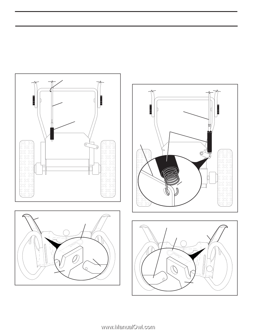
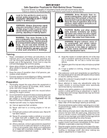
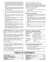
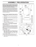
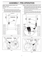
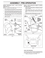
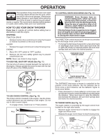
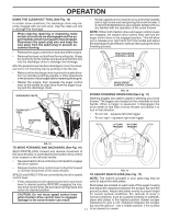
ASSEMBLY / PRE-OPERATION INSTALL TRACTION DRIVE CONTROL ROD (See Figs. 3 and 4) The traction drive control rod is installed on the snow thrower. 1. Remove plastic tie securring rod to lower handle. 2. With top end of rod positioned under left side of control panel, push rod down and insert top end of rod into hole in drive control bracket. Secure with retainer spring. PLASTIC TIE INSTALL AUGER CONTROL ROD (See Figs. 5 and 6) 1. Retrieve vinyl sleeve and spring from bag of parts and retrieve the auger control rod from carton chute tray. Slide straight rod end through the small hole in the vinyl sleeve. Hook spring in hole in rod end. 2. Hook end of spring into control arm with loop opening up as shown. (See Fig. 5) 3. With top end of rod positioned under right side of control panel, push down on rod and insert end of rod into hole in auger control bracket. Secure with retainer spring. TRACTION DRIVE CONTROL ROD VINYL SLEEVE CONTROL ARM AUGER CONTROL ROD VINYL SLEEVE FIG. 3 TRACTION DRIVE CONTROL LEVER RETAINER SPRING TRACTION DRIVE CONTROL ROD DRIVE CONTROL BRACKET FIG. 4 6 LOOP OPENING UP FIG. 5 AUGER CONTROL ROD AUGER CONTROL RETAINER LEVER SPRING AUGER CONTROL BRACKET FIG. 6
-
 1
1 -
 2
2 -
 3
3 -
 4
4 -
 5
5 -
 6
6 -
 7
7 -
 8
8 -
 9
9 -
 10
10 -
 11
11 -
 12
12 -
13
-
14
-
15
-
16
-
17
-
18
-
19
-
20
-
21
-
22
-
23
-
24
-
25
-
26
-
27
-
28
-
29
-
30
-
31
-
32
-
33
-
34
-
35
-
36
-
37
-
38
-
39
-
40
-
41
-
42
-
43
-
44
 |
 |