Poulan PP8527ES User Manual - Page 15
Service And Adjustments
 |
View all Poulan PP8527ES manuals
Add to My Manuals
Save this manual to your list of manuals |
Page 15 highlights
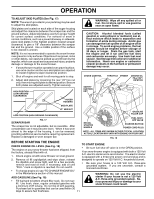
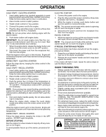
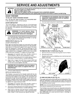
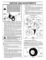
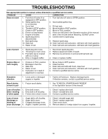
SERVICE AND ADJUSTMENTS WARNING: To avoid serious injury, before performing any service or adjustments: 1. Be sure throttle is in STOP position. 2. Remove safety ignition key. 3. Make sure the augers and all moving parts have completely stopped. 4. Disconnect spark plug wire from spark plug and place wire where it cannot contact plug. SNOW THROWER TO ADJUST SNOW THROWER HEIGHT See "TO ADJUST SKID PLATES" and "SCRAPER BAR" in the Operation section of this manual. CHUTE DEFLECTOR The chute deflector, attached to the top of the discharge chute, is provided to direct discharging snow away from the operator. If the deflector becomes damaged, it should be replaced. WARNING: To avoid serious injury, never operate your snow thrower with the deflector removed or damaged. CAUTION: Do not substitute. Use only original equipment capscrew/shear bolts as supplied with your snow thrower. 4. Connect spark plug wire to spark plug. 1/4-20 LOCKNUT 1/4-20 x 1-5/8 CAPSCREW / SHEAR BOLT IMPELLER HUB IMPELLER SHAFT 1/4-20 x 2 SHOULDER / SHEAR BOLT • To change direction and/or distance snow is discharged, see "TO CONTROL SNOW DISCHARGE" in the Operation section of this manual. SHEAR BOLTS (See Fig. 19) AUGER SHEAR BOLTS Both right and left-hand augers are secured to the auger shaft with a shoulder/shear bolt and hex nut. Should a foreign object or ice become lodged in the augers, the shear bolts are designed to break, preventing damage to any other components. If one or both augers do not turn when auger control lever is engaged, check to see if one or both of the bolts have sheared. To replace the shear bolts: 1. Disengage all controls and move throttle control to STOP position. Wait for all moving parts to stop. 2. Disconnect spark plug wire from spark plug and place wire where it cannot come in contact with plug. 3. Align hole in auger hub with hole in auger shaft and install a new 1/4-20 x 2" shoulder/shear bolt. Install 1/4-20 lock nut and tighten securely. AUGER HUB 1/4-20 LOCKNUT AUGER HUB AUGER SHAFT FIG. 19 TO REMOVE BELT COVER (See Fig. 20) 1. Remove the two screws securing belt cover to frame. 2. Remove belt cover. • Replace belt cover by installing cover and screws and tighten securely. CAUTION: Do not substitute. Use only original equipment shear bolts as supplied with your snow thrower. 4. Connect spark plug wire to spark plug. IMPELLER SHEAR BOLTS The impeller is secured to the impeller shaft with two (2) FRAME BELT COVER SCREWS capscrew/shear bolts and hex nuts. Should a foreign object or ice become lodged in the impeller, the capscrews are designed to break, preventing damage to any other com- FIG. 20 TO REPLACE BELTS (See Fig. 21) ponents. If impeller does not turn when auger control lever The auger and traction drive belts are not adjustable. If the is engaged, check to see if the capscrews have sheared. belts are damaged or begin to slip from wear, they should To replace the capscrew/shear bolts: be replaced. It is recommended that the belt(s) be replaced 1. Disengage all controls and move throttle control to by a qualified service center. STOP position. Wait for all moving parts to stop. NOTE: It is recommended that both the auger and traction 2. Disconnect spark plug wire from spark plug and place drive belt be replaced at the same time. wire where it cannot come in contact with plug. The V-belts on your snow thrower are of special construction 3. Align holes in impeller hub with holes in impeller shaft and install two (2) new 1/4-20 x 1-5/8" capscrew/shear bolts. Install 1/4-20 locknuts and tighten securely. and should be replaced by original equipment manufacturer (OEM) belts available from your nearest dealer. Using other than OEM belts can cause personal injury or damage to 15 the snow thrower.
-
 1
1 -
2
-
3
-
4
-
5
-
6
-
7
-
8
-
9
-
 10
10 -
 11
11 -
 12
12 -
 13
13 -
 14
14 -
 15
15 -
 16
16 -
 17
17 -
 18
18 -
 19
19 -
 20
20
 |
 |