Poulan PP8527ES User Manual - Page 6
Install Discharge Chute / Chute Rotater, Head See Fig. 7, Check Tire Pressure, Install Auger Control
 |
View all Poulan PP8527ES manuals
Add to My Manuals
Save this manual to your list of manuals |
Page 6 highlights
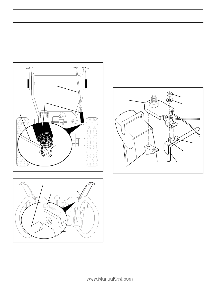
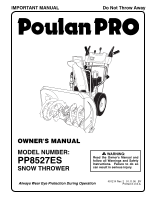
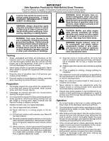
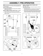
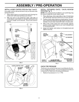
ASSEMBLY / PRE-OPERATION INSTALL AUGER CONTROL ROD (See Figs. 5 and 6) The auger control rod has the short loop on the end of the spring as shown. 1. Slide rubber sleeve up rod and hook end of spring into control arm with loop opening up as shown. 2. With top end of rod positioned under right side of control panel, push down on rod and insert end of rod into hole in auger control bracket. Secure with retainer spring. CONTROL ARM AUGER CONTROL ROD RUBBER SLEEVE INSTALL DISCHARGE CHUTE / CHUTE ROTATER HEAD (See Fig. 7) NOTE: The multi-wrench provided in your parts bag may be used to install the chute rotater head. 1. Place discharge chute assembly on top of chute base with discharge opening toward front of snow thrower. 2. Position chute rotater head over chute bracket. If necessary, rotate chute assembly to align square and pin on underside of chute rotater head with holes in chute bracket. 3. With chute rotater head and chute bracket aligned, position chute rotater head on pin and threaded stud of mounting bracket. 4. Install 3/8 washer and locknut on threaded stud and tighten securely. CHUTE ROTATER HEAD 3/8 LOCKNUT 3/8 WASHER LOOP OPENING UP FIG. 5 AUGER CONTROL ROD AUGER CONTROL RETAINER LEVER SPRING PIN THREADED STUD CHUTE ALIGN BEFORE BRACKET TIGHTENING LOCKNUT FIG. 7 ROTATER HEAD MOUNTING BRACKET CHECK TIRE PRESSURE The tires on your snow thrower were overinflated at the factory for shipping purposes. Correct and equal tire pressure is important for best snow throwing performance. • Reduce tire pressure to 14-17 PSI. AUGER CONTROL BRACKET FIG. 6 6
-
 1
1 -
 2
2 -
 3
3 -
 4
4 -
 5
5 -
 6
6 -
 7
7 -
 8
8 -
 9
9 -
 10
10 -
 11
11 -
 12
12 -
13
-
14
-
15
-
16
-
17
-
18
-
19
-
20
 |
 |