Poulan PPCRT17 Owner Manual - Page 5
UNPACKING CARTON See Fig. 2, INSTALL HANDLE See Figs. 3, 4, and 5
 |
View all Poulan PPCRT17 manuals
Add to My Manuals
Save this manual to your list of manuals |
Page 5 highlights
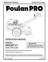
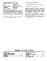
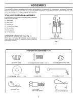
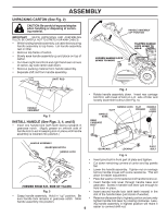
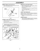
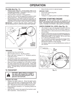
ASSEMBLY UNPACKING CARTON (See Fig. 2) CAUTION: Be careful of exposed staples when handling or disposing of cartoning material. IMPORTANT: WHEN UNPACKING AND ASSEMBLING TILLER, BE CAREFUL NOT TO STRETCH OR KINK CABLES. • While holding handle assembly, cut cable ties securing handle assembly to top frame. Let handle assembly rest on tiller. • Remove top frame of carton. • Slowly ease handle assembly up and place on top of carton. • Cut down right hand front and right hand rear corners of carton, lay side carton wall down. • Remove packing material from handle assembly. • Separate shift rod from handle assembly. LOOSEN HANDLE LOCK LEVER TO MOVE SHIFT ROD HANDLE ASSEMBLY "UP" POSITION TIGHTEN HANDLE LOCK LEVER TO HOLD Fig. 4 • Rotate handle assembly down. Insert rear carriage carton_1 bolt first, with head of bolt on L.H. side of tiller and loosely assemble locknut (See Fig. 5). HANDLE ASSEMBLY Fig. 2 SLOT HANDLE BASE HANDLE LOCK FLAT HANDLE WASHER LOCK LEVER INSTALL HANDLE (See Figs. 3, 4, and 5) • Insert one handle lock (with teeth facing outward) in gearcase notch. (Apply grease on smooth side of handle lock to aid in keeping lock in place until handle assembly is lowered into position.) HANDLE ASSEMBLY GEARCASE NOTCH HANDLE LOCK REAR CARRIAGE BOLT GEARCASE handles_34 LOCKNUT Fig. 5 PIVOT BOLT • Insert pivot bolt in front part of plate and tighten. • Cut down remaining corners of carton and lay panels flat. • Lower the handle assembly. Tighten nut on carriage bolt so handle moves with some resistance. This will allow for easier adjustment. • Place flat washer on threaded end of handle lock lever. • Insert handle lock lever through handle base and (VIEWED FROM R.H. SIDE OF TILLER) gearcase. Screw in handle lock lever just enough to hold lever in place. Fig. 3 • Grasp handle assembly. Hold in "up" position. Be sure handle lock remains in gearcase notch. Slide handle assembly into position. • Insert second handle lock (with teeth inward) in the slot of the handle base (just inside of washer). • Raise handle assembly to highest position and securely tighten handle lock lever by rotating clockwise. Leaving handle assembly in highest position will make it 5 easier to connect shift rod.
-
 1
1 -
 2
2 -
 3
3 -
 4
4 -
 5
5 -
 6
6 -
 7
7 -
 8
8 -
 9
9 -
 10
10 -
 11
11 -
12
-
13
-
14
-
15
-
16
-
17
-
18
-
19
-
20
-
21
-
22
-
23
-
24
-
25
-
26
-
27
-
28
-
29
-
30
-
31
-
32
-
33
-
34
-
35
-
36
-
37
-
38
-
39
-
40
 |
 |