Poulan PR120N20S Owner Manual - Page 7
Maintenance, Assembly
 |
View all Poulan PR120N20S manuals
Add to My Manuals
Save this manual to your list of manuals |
Page 7 highlights
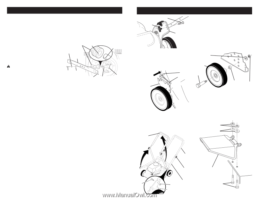
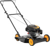
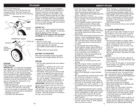
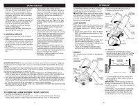
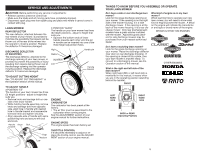
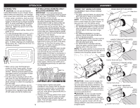
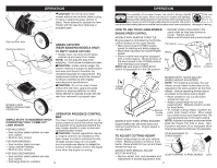
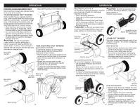
MAINTENANCE LAWN MOWER Always observe safety rules when performing any maintenance. TIRES • Keep tires free of gasoline, oil, or insect control chemicals which can harm rubber. • Avoid stumps, stones, deep ruts, sharp objects and other hazards that may cause tire damage. 5. Use block of wood between blade and lawn mower housing and tighten the blade bolt, turning clockwise. • The recommended tightening torque is 35-40 ft. lbs. (47-54 Nm). IMPORTANT: Blade bolt is heat treated. If bolt needs replacing, replace only with approved bolt. Blade adapter Key Lockwasher Crankshaft keyway BLADE CARE For best results, blade must be kept sharp. Replace a bent or damaged blade. CAUTION: Use only a replacement blade approved by the manufacturer of your mower. Using a blade not approved by the manufacturer of your mower is hazardous, could damage your mower and void your warranty. TO REMOVE BLADE 1. Disconnect spark plug wire from spark plug and place wire where it cannot come in contact with plug. 2. Turn lawn mower on its side. Make sure air filter and carburetor are up. 3. Use a wood block between blade and mower housing to prevent blade from turning when removing blade bolt. NOTE: Protect your hands with gloves and/or wrap blade with heavy cloth. 4. Remove blade bolt by turning counter- clockwise. 5. Remove blade and attaching hardware (bolt, lock washer, hardened washer). NOTE: Remove the blade adapter and check the key inside hub of blade adapter. The key must be in good condition to work properly. Replace adapter if damaged. TO REPLACE BLADE 1. Position the blade adapter on the engine crankshaft. Be sure key in adapter and crankshaft keyway are aligned. 2. Position blade on the blade adapter aligning the two (2) holes in the blade with the raised lugs on the adapter. 3. Be sure the trailing edge of blade (opposite sharp edge) is up toward the engine. 4. Install the blade bolt with the lock washer and hardened washer into blade adapter and crankshaft. Blade Blade Hardened bolt washer Trailing edge Belt Crankshaft retainer TO SHARPEN BLADE NOTE: We do not recommend sharpening blade - but if you do, be sure the blade is balanced. An unbalanced blade will cause eventual damage to lawn mower or engine. • The blade can be sharpened with a file or on a grinding wheel. Do not attempt to sharpen while on the mower. • To check blade balance, drive a nail into a beam or wall. Leave about one inch of the straight nail exposed. Place center hole of blade over the head of the nail. If blade is balanced, it should remain in a horizontal position. If either end of the blade moves downward, sharpen the heavy end until the blade is balanced. ENGINE Read the maintenance section of your engine manual. LUBRICATION Change the oil after the first two hours of operation and every 25 hours thereafter or at least once a year if the mower is not used for 25 hours in one year. Refer to engine manual. NOTE (B&S W26 engines with Synthetic oil ONLY): An oil change is not required but if you desire to change the oil follow the procedure below. 18 ASSEMBLY Knob Bolt Handle bracket 3 POSITION "QUICK" HANDLES • Raise lower handle section to operating position and squeeze the bottom ends of lower handle towards each other until the pin in handle can be inserted into one of the three height adjustment holes. Handle pin SQUEEZE ASSEMBLE WHEELS Cutting height is determined by assembling wheels in one of four possible positions on the mower housing. All wheels must be in the same height position for even cutting. • For each wheel, assemble shoulder bolt, wheel and spacer as shown. • Assemble 1-1/4" diam. washer (front only) and 3/8-16 locknut on inside of mower housing and tighten securely. Flat washer (front only) Wheel Bolt Handle adjustment bracket DOMED HOUSING MODELS ONLY: • Raise handles until lower handle section locks into place in mowing position. • Insert bolt through handle and bracket and secure with nut. A 1/2" wrench will be required. Operator MOWING presence POSITION control bar LIFT UP Spacer Nut INSTALL DISCHARGE GUARD (SIDE DISCHARGE MODELS ONLY) • Place discharge guard on top of lawn mower discharge opening. • Install two (2) hex bolts through housing and discharge guard. • Install two (2) washers and two (2) 1/4-20 locknuts. Tighten securely. Locknuts Washers LIFT UP Bolt Upper handle Handle knob Discharge guard Lower handle Nut Bracket 7 Hex bolts
-
 1
1 -
 2
2 -
 3
3 -
 4
4 -
 5
5 -
 6
6 -
 7
7 -
 8
8 -
 9
9 -
 10
10 -
 11
11 -
 12
12
 |
 |