Poulan U4000C User Manual - Page 4
Assembly
 |
View all Poulan U4000C manuals
Add to My Manuals
Save this manual to your list of manuals |
Page 4 highlights
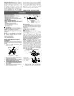
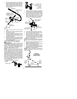
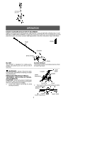
SPECIAL NOTICE: Exposure to vibrations through prolonged use of gasoline powered hand tools could cause blood vessel or nerve damage in the fingers, hands, and joints of people prone to circulation disorders or abnormal swellings. Prolonged use in cold weather has been linked to blood vessel damage in otherwise healthy people. If symptoms occur such as numbness, pain, loss of strength, change in skin color or texture, or loss of feel- ing in the fingers, hands, or joints, discontinue the use of this tool and seek medical attention. An anti-vibration system does not guarantee the avoidance of these problems. Users who operatepower tools on a continual and regular basis must monitor closely their physical condition and the condition of this tool. SAVE THESE INSTRUCTIONS ASSEMBLY CARTON CONTENTS Check carton contents for the following: S Brushcutter attachment S Handlebar (with clamp and knob) S Handlebar clamp base (with spacer tabs) S Shoulder strap S Upper shoulder strap clamp S Lower shoulder strap clamp (with spacer tabs) S Handlebar clamp screws (4) S Shoulder strap clamp screws (2) S Attachment hanger S Hex wrench WARNING: If received assembled, re- peat all steps to ensure your unit is properly assembled and all fasteners are secure. Examine parts for damage. Do not use damaged parts. NOTE: If you need assistance or find that parts are missing or damaged, call 1-800-554-6723. TOOLS REQUIRED S Hex wrench (provided) INSTALLING BRUSHCUTTER ATTACHMENT CAUTION: When removing or installing attachments, place the unit on a flat surface for stability. 1. Loosen the coupler by turning the knob counterclockwise. Coupler LOOSEN Coupler Primary Hole Guide Recess Upper Shaft Locking/ Release Button Lower Attachment WARNING: Make sure the locking/re- lease button is locked in the primary hole and the knob is securely tightened before operating the unit. HANDLEBAR ASSEMBLY DANGER: RISK OF CUT. To avoid serious injury, the barrier portion of the handlebar must be installed as shown on the upper shaft of the powerhead to provide a barrier between operator and the spinning blade. Attach shaft clamp above arrow on safety warning decal on the upper shaft (powerhead end of unit). Ensure handlebar is positioned on handlebar clamp between the arrows on the handlebar decal. NOTE: The shaft clamp base has four spacer tabs attached. These tabs are provided to adapt this attachment for use with powerheads that have a 1" diameter upper shaft (the shaft clamp will not tighten down securely on the 1" diameter upper shaft without using these spacer tabs). The tabs must be broken off completely before use and placed over the screw holes on the clamp base. These tabs are not needed for powerheads with a 7/8" upper shaft. HANDLEBAR CLAMP BASE Spacer Tabs TIGHTEN Knob 2. Remove the shaft cap from the brushcutter attachment (if present). 3. Position locking/release button of attach- ment into guide recess of coupler. 4. Push the attachment into the coupler until the locking/release button snaps into the primary hole. 5. Before using the unit, tighten the knob se- curely by turning clockwise. Spacer Tabs positioned for use on 1" diameter upper shaft 1. Place the shaft clamp over the upper shaft above the arrow on the safety decal. 4
-
 1
1 -
 2
2 -
 3
3 -
 4
4 -
 5
5 -
 6
6 -
 7
7 -
 8
8 -
 9
9 -
 10
10
 |
 |
