Poulan U4000C User Manual - Page 5
Shoulder Strap Assembly
 |
View all Poulan U4000C manuals
Add to My Manuals
Save this manual to your list of manuals |
Page 5 highlights
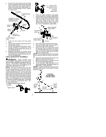
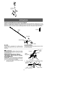
2. Position the clamp base under the upper shaft and align the shaft clamp and clamp base screw holes (use spacer tabs between shaft clamp and clamp base if necessary to secure clamp, i.e. for 1" diameter upper shaft). Handlebar POWERHEAD END Handlebar Clamp between arrows on handlebar decal Clamp Knob Shaft Clamp Clamp Base Screws Arrow on Safety Decal ATTACHMENT END 3. Insert the four screws into the screw holes. 4. Secure shaft clamp by tightening screws with the hex wrench. 5. Position the handlebar as shown, ensuring the handlebar is positioned on the handlebar clamp between the arrows on the handlebar decal. 6. Retighten handlebar by turning clamp knob clockwise until handlebar is secure and stationary in clamp (clamp knob cannot be overtightened). SHOULDER STRAP ASSEMBLY WARNING: Proper shoulder strap and handlebar adjustments must be made with the engine completely stopped beforeusing unit. The shoulder strap clamp must be installed as shown above the handlebar on the upper shaft (powerhead end of unit). NOTE: The lower shoulder strap clamp has two spacer tabs attached. These tabs are provided to adapt this attachment for use with powerheads that have a 1" (2.5 cm) diameter upper shaft (the shoulder strap clamp will not tighten down securely on the 1" (2.5 cm) diameter upper shaft without using these spacer tabs). The tabs must be broken off completely before use and placed over the screw holes on the lower shoulder strap clamp. These tabs are not needed for powerheads with a 7/8" (2.2 cm) upper shaft. LOWER SHOULDER STRAP CLAMP Spacer Tabs Spacer Tabs positioned for use on 1" (2.5 cm) diameter upper shaft 1. Place the upper shoulder strap clamp over the upper shaft above the handlebar. 2. Position the lower shoulder strap clamp under the upper shaft and align the upper and lower clamp screw holes (use spacer tabs between upper and lower clamps if necessary to secure clamp, i.e. for 1" (2.5 cm) diameter upper shaft). POWERHEAD END Upper Shoulder Strap Clamp Lower Shoulder Strap Clamp ATTACHMENT END Screws 3. Insert two screws into the screw holes. 4. Secure shoulder strap clamp by tighten- ing screws with the hex wrench. 5. Insert your right arm and head through the shoulder strap and allow it to rest on your left shoulder. Make sure the danger sign is on your back and the hook is to the right side of your waist. NOTE: A one-half twist is built in the shoulder strap to allow the strap to rest flat on the shoulder. 6. Adjust the strap, allowing the hook to be about 6 inches below the waist. 7. Fasten the strap hook to the clamp and lift the tool to the operating position. 8. Try on shoulder strap and adjust for fit and balance before starting the engine or beginning a cutting operation. NOTE: It may be necessary to relocate the shoulder strap clamp on the shaft for proper balancing of unit. HARNESS ADJUSTMENT FOR BALANCE 6 inches (15 cm) below waist 30 inches (76 cm) 4 -- 12 inches (10 -- 30 cm) above ground 5
-
 1
1 -
 2
2 -
 3
3 -
 4
4 -
 5
5 -
 6
6 -
 7
7 -
 8
8 -
 9
9 -
 10
10
 |
 |
