ProForm 1095 Zlt Treadmill Uk Manual - Page 10
Identify the Storage Latch 55. Remove the tie
 |
View all ProForm 1095 Zlt Treadmill manuals
Add to My Manuals
Save this manual to your list of manuals |
Page 10 highlights
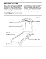
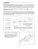
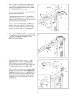
11. Identify the Storage Latch (55). Remove the tie from the end of the tube. Make sure that the sleeve has been slid over hole 1 and that the Latch Knob (54) is locked into hole 1. Pull on the sleeve to make sure that it is locked into place. 11 Tube 54 Hole 1 Sleeve 55 12. Raise the Frame (53) to the position shown. Have a second person hold the Frame until 12 this step is completed. Orient the Latch Assembly (55) so that the large barrel and the Latch Knob (54) are in the positions shown. Attach the Latch Bracket (68) to the bracket on the Base (80) with two 3/8" x 2" Bolts (4) and two 3/8" Nuts (8). Attach the upper end of the Latch Assembly (55) to the bracket on the Frame (53) with a 3/8" x 2" Bolt (4) and a 3/8" Nut (8). Note: It may be necessary to move the Frame back and forth to align the Latch Assembly with the bracket. Lower the Frame (53) (see HOW TO LOWER THE TREADMILL FOR USE on page 18). 53 8 4 55 54 Large Barrel 68 80 8 4 13. Make sure that all parts are properly tightened before you use the treadmill. If there are sheets of clear plastic on the treadmill decals, remove the plastic. To protect the floor or carpet, place a mat under the treadmill. Keep the included hex key in a secure place; the hex key is used to adjust the walking belt (see pages 20 and 21). 10
-
 1
1 -
2
-
3
-
4
-
 5
5 -
 6
6 -
 7
7 -
 8
8 -
 9
9 -
 10
10 -
 11
11 -
 12
12 -
 13
13 -
 14
14 -
 15
15 -
16
-
17
-
18
-
19
-
20
-
21
-
22
-
23
-
24
-
25
-
26
-
27
-
28
 |
 |
