ProForm 1095 Zlt Treadmill Uk Manual - Page 9
If The Connectors Are Not Con
 |
View all ProForm 1095 Zlt Treadmill manuals
Add to My Manuals
Save this manual to your list of manuals |
Page 9 highlights
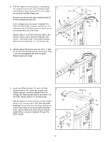
8. Have a second person hold the console assembly near the Right Upright (72). Connect the Upright Wire (78) to the console wire. See the inset drawing. The connectors should slide together easily and snap into place. If they do not, turn one connector and try again. IF THE CONNECTORS ARE NOT CONNECTED PROPERLY, THE CONSOLE MAY BE DAMAGED WHEN THE POWER IS TURNED ON. Remove the wire tie from the Upright Wire. Then, insert the connectors into the Right Upright (72). Set the console assembly on the Right Upright (72) and the Left Upright (not shown). Attach the console assembly with four 5/16" x 1" Bolts (5) and four 5/16" Star Washers (7) (only two are shown); start all four Bolts before tightening any of them. 9. Insert the Book Rack (84) into the console assembly; it may be helpful to rock the Book Rack up and down as you insert it. Attach the Book Rack with eight 3/4" Screws (10); start all eight Screws before tightening any of them. See steps 5 and 7. Tighten the 3/8" x 4" Bolts (6). 8 Console Wire 78 7 5 72 Console Assembly Console Wire 7 78 5 Wire Tie 9 84 Console Assembly 10 10 10 10. If necessary, press the Left Tray (86) and the Right Tray (85) into the top of the console assembly. 10 Console 86 Assembly 85 9
-
 1
1 -
2
-
3
-
 4
4 -
 5
5 -
 6
6 -
 7
7 -
 8
8 -
 9
9 -
 10
10 -
 11
11 -
 12
12 -
 13
13 -
 14
14 -
15
-
16
-
17
-
18
-
19
-
20
-
21
-
22
-
23
-
24
-
25
-
26
-
27
-
28
 |
 |
