ProForm 235 Csx English Manual - Page 20
Fcc Information
 |
View all ProForm 235 Csx manuals
Add to My Manuals
Save this manual to your list of manuals |
Page 20 highlights
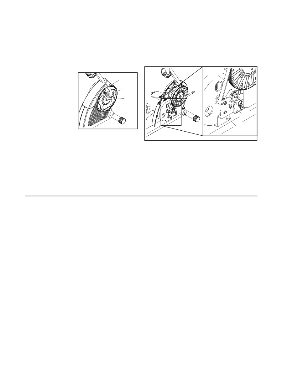
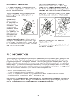
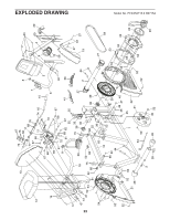
HOW TO ADJUST THE DRIVE BELT If the pedals slip while you are pedaling, even while the resistance is adjusted to the highest level, the drive belt may need to be adjusted. To adjust the drive belt, you must remove the right pedal, the right lock ring, and the right shield as described below. Using an adjustable wrench, turn the Right Pedal (29) counterclockwise and remove it. Then, using a standard screwdriver, release the tabs around the edge of the right Lock Ring (23), and then remove it from the Right Shield (22). 22 29 23 See assembly step 5 on page 9. Using a standard screwdriver, release the tabs along the bottom edges of the Rear and Front Upright Covers (19, 20), remove the two M4 x 12mm Screws (57), and then remove the Rear and Front Upright Covers. See the EXPLODED DRAWING on page 23. Remove all of the screws from the Left and Right Shields (21, 22); there are two sizes of screws in the shields-note which size of screw you remove from each hole. Then, gently remove the Right Shield. Next, loosen the Adjustment Screw (47). Then, tighten the Idler Screw (45) until the Drive Belt (59) is tight. 59 47 45 When the Drive Belt (59) is tight, tighten the Adjustment Screw (47). Then, reattach the left and right shields, the right lock ring, and the right pedal. FCC INFORMATION This equipment has been tested and found to comply with the limits for a Class B digital device, pursuant to part 15 of the FCC Rules. These limits are designed to provide reasonable protection against harmful interference in a residential installation. This equipment generates, uses, and can radiate radio frequency energy and, if not installed and used in accordance with the instructions, may cause harmful interference to radio communications. However, there is no guarantee that interference will not occur in a particular installation. If this equipment does cause harmful interference to radio or television reception, which can be determined by turning the equipment off and on, try to correct the interference by one or more of the following measures: • Reorient or relocate the receiving antenna. • Increase the separation between the equipment and the receiver. • Connect the equipment into an outlet on a circuit different from that to which the receiver is connected. • Consult the dealer or an experienced radio/TV technician for help. FCC CAUTION: To assure continued compliance, use only shielded interface cables when connecting to computer or peripheral devices. Changes or modifications not expressly approved by the party responsible for compliance could void the user's authority to operate this equipment. 20
-
 1
1 -
2
-
3
-
4
-
5
-
6
-
7
-
8
-
9
-
10
-
11
-
12
-
13
-
14
-
 15
15 -
 16
16 -
 17
17 -
 18
18 -
 19
19 -
 20
20 -
 21
21 -
 22
22 -
 23
23 -
 24
24
 |
 |