ProForm 485 Instruction Manual - Page 6
Maintenance And Troubleshooting
 |
View all ProForm 485 manuals
Add to My Manuals
Save this manual to your list of manuals |
Page 6 highlights
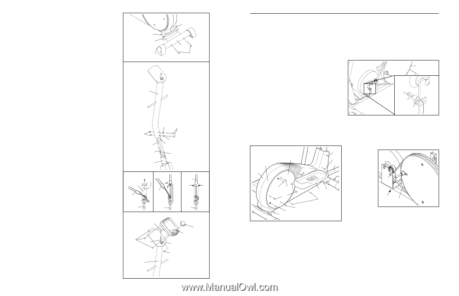
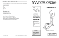
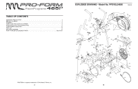
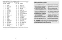
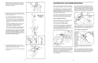
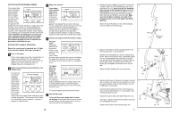
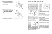
2. Whilst another person lifts the back of the Frame (1) slightly, attach the Rear Stabiliser (9) to the Frame with two M10 x 75mm Carriage Bolts (34) and two M10 Nylon Locknuts (33). 3. Whilst another person holds the Upright (2) near the Frame (1) as shown, connect the Upper Wire (44) to the Reed Switch Wire (53). Next, connect the Resistance Cable (45) to the Lower Resistance Cable (65) in the following way: • See drawing A. Pull up on the metal bracket, and insert the tip of the Resistance Cable (45) into the wire clip on the Lower Resistance Cable (65) as shown. • See drawing B. Firmly pull the Resistance Cable (45) and slide it into the metal bracket on the Lower Resistance Cable (65) as shown. • See drawing C. Using pliers, squeeze the prongs on the upper end of the metal bracket together. Slide the Upright (2) onto the Frame (1); make sure not to pinch the wires or cables. Attach the Upright with two M10 x 74mm Button Bolts (67), two M10 Nylon Locknuts (33), and two M10 Split Washers (59). Do not tighten the Button Bolts yet. 4. Connect the Upper Wire (44) to the wire on the Console (23). Next, attach the Console to the Upright (2) with four M4 x 12mm Screws (42). Press the Resistance Knob (63) onto the Resistance Control (45). 2 33 1 3 2 33 9 34 Make sure not to pinch the wires or cables. 33 45 65 1 59 67 59 44 53 A B Metal Bracket 45 45 C 45 65 65 65 4 Console Wire 42 44 63 23 45 42 2 6 MAINTENANCE AND TROUBLESHOOTING Inspect and properly tighten all parts of the elliptical trainer regularly. Replace any worn parts immediately. The elliptical trainer can be cleaned with a soft cloth and a small amount of mild detergent. Do not use abrasives or solvents. To prevent damage to the console, keep liquids away from the console and keep the console out of direct sunlight. When storing the elliptical trainer, remove the batteries from the console. Keep the elliptical trainer in a clean, dry location, away from moisture and dust. CONSOLE TROUBLESHOOTING If the console does not function properly, replace the batteries (see assembly step 9 on page 8). HOW TO ADJUST THE REED SWITCH If the console does not display correct feedback, the reed switch should be adjusted. To adjust the reed switch, first see assembly step 8 on page 8 and remove the Pedals (13, 14). Next, see step 7 on page 7 and remove the Pedal Arms (11, 12). 64 15 52 4 12 3 64 69 70 51 69 70 64 14 64 52 Next, remove all of the Screws (51, 70) from the right Pedal Disc (15), and slide the Pedal Disc off. Remove all Screws (52, 64, 69) from the Right Side Shield (4), and remove the Right Side Shield. Remove all Screws (52) from the Left Side Shield (3), and remove the Left Side Shield. Next, see the drawing below and locate the Reed Switch (53). Loosen, but do not remove, the indicated Screw (52). Slide the Reed Switch slightly toward or away from the Magnet (58) on the flywheel. Retighten the Screw. Turn the left Pedal Disc (15) for a moment. Repeat until the console displays correct feedback. 15 58 53 52 When the Reed Switch (53) is correctly adjusted, reattach the Side Shields (3, 4), the right Pedal Disc (15), the Pedal Arms (11, 12), and the Pedals (13, 14). HOW TO ADJUST THE DRIVE BELT If you can feel the pedals slip whilst you are pedaling, even when the resistance knob is turned to the maxi- 68 mum setting, the Drive Belt (19) may need to be 62 19 adjusted. To adjust the Drive Belt, you must remove both side shields. See the instructions at the left and remove the side shields. Next, loosen the M8 x 22mm Flat Head Screw (68) and turn the Idler Adjustment Bolt (62) until the Drive Belt (19) is tight. Once the Drive Belt is tight, tighten the Flat Head Screw. Reattach the side shields. 11
-
 1
1 -
 2
2 -
 3
3 -
 4
4 -
 5
5 -
 6
6 -
 7
7 -
 8
8
 |
 |