ProForm 530 User Manual - Page 6
Assembly - i treadmill
 |
View all ProForm 530 manuals
Add to My Manuals
Save this manual to your list of manuals |
Page 6 highlights
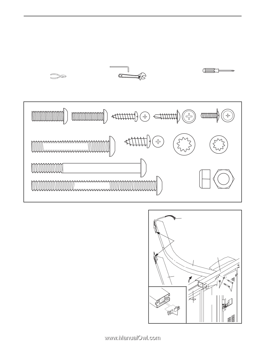
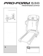
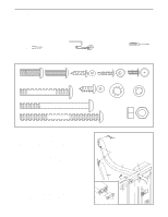
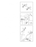
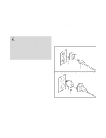
ASSEMBLY Assembly requires two persons. Set the treadmill in a cleared area and remove all packing materials. Do not dispose of the packing materials until assembly is completed. Note: The underside of the treadmill walking belt is coated with high-performance lubricant. During shipping, a small amount of lubricant may be transferred to the top of the walking belt or the shipping carton. This is a normal condition and does not affect treadmill performance. If there is lubricant on top of the walking belt, simply wipe off the lubricant with a soft cloth and a mild, non-abrasive cleaner. Assembly requires the included allen wrenches and your own phillips screwdriver , wire cutters , and adjustable wrench . For help identifying assembly hardware, see the drawings below. Note: If a part is not found in the part bags, check to see if the part has been preattached. 5/16" x 1" Bolt (122)-4 1/4" x 1" Bolt (71)-4 3/4" Screw (6)-7 3/4" Tek Screw (47)-8 1/2" Ground Screw (114)-1 Wheel Bolt (107)-2 3 1/2" Bolt (90)-4 Pulse Bar Screw (68)-4 5/16" Star 1/4" Star Washer Washer (84)-4 (92)-4 4" Bolt (112)-2 Wheel Nut (21)-2 1. With the help of another person, carefully tip the treadmill onto its left side. Partially fold the Frame (54) so that 1 the treadmill is more stable. Do not fully fold the tread- mill until it is completely assembled. Identify the Left Upright (81) and the Right Upright (82); the indicated brackets on the Uprights overhang toward the center of the treadmill. Make sure that there are two U-Nuts (105) (see the inset drawing) in the lower end of each Upright. Feed the Wire Harness (83) into the lower end of the Right Upright, and pull the Wire Harness out of the hole in bracket on the Right Upright. Note: There may be a tie on the Wire Harness to help you pull it out of the hole. Attach the Right Upright (82) to the right side of the Base (109) with two 3 1/2" Bolts (90) and two 5/16" Star Washers (84). Do not tighten the Bolts yet. Be careful not to damage the Wire Harness (83). Attach the Left Upright (81) to the left side of the Base in the same way. Note: There is not a wire harness on the left side. 6 83 Brackets 82 81 54 105 109 84 90
-
 1
1 -
 2
2 -
 3
3 -
 4
4 -
 5
5 -
 6
6 -
 7
7 -
 8
8 -
 9
9 -
 10
10 -
 11
11 -
 12
12 -
13
-
14
-
15
-
16
-
17
-
18
-
19
-
20
-
21
-
22
-
23
-
24
-
25
-
26
-
27
-
28
-
29
-
30
-
31
-
32
-
33
-
34
 |
 |