ProForm 545 Ekg Instruction Manual - Page 6
Handlebar Arm with two M8 x 45mm Button Bolts
 |
View all ProForm 545 Ekg manuals
Add to My Manuals
Save this manual to your list of manuals |
Page 6 highlights
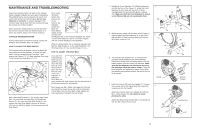
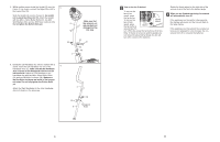
5. Whilst another person holds the Upright (2) near the 5 Frame (1) as shown, connect the Upper Wire (44) to the Lower Wire (70). Slide the Upright (2) onto the Frame (1); be careful not to pinch the Wires (44, 70). Attach the Upright with two M10 x 74mm Button Bolts (27), two M10 Split Washers (59), and two M10 Nylon Locknuts (33). Do not tighten the Button Bolts yet. 2 Make sure that the wires do not get pinched and damaged during this step. 33 1 59 27 44 70 6. Identify the Left Handlebar (6), which is marked with a sticker. Insert the Left Handlebar into one of the 6 Handlebar Arms (5); make sure that the Handlebar Arm is turned so the hexagonal holes are on the indicated side. Attach the Left Handlebar to the Handlebar Arm with two M8 x 45mm Button Bolts (50) and two M8 Nylon Locknuts (38). Make sure that the Nylon Locknuts are inside of the hexago- nal holes. Do not fully tighten the Button Bolts yet. Attach the Right Handlebar to the other Handlebar Arm (not shown) in the same way. 6 38 50 Hexagonal 5 Holes 5 Turn on the fan if desired. To turn on the fan at low speed, press the fan button. To turn on the fan at high speed, press the fan button a Fan Button Thumb Wheel second time. To turn off the fan, press the fan button a third time. Note: If the fan is turned on and the pedals are not moved for about half a minute, the fan will turn off to conserve the batteries. Rotate the thumb wheel on the right side of the console to pivot the fan to the desired angle. 6 When you are finished exercising, the console will automatically turn off. If the pedals are not moved for a few seconds, the displays will pause and the time will flash in the large display. If the pedals are not moved and the console buttons are not pressed for a few minutes, the console will turn off to conserve the batteries. 6 11
-
 1
1 -
 2
2 -
 3
3 -
 4
4 -
 5
5 -
 6
6 -
 7
7 -
 8
8
 |
 |
