ProForm 545 Uk Manual - Page 6
Extension Leg 34 with a Handrail Bolt 91, a Handrail
 |
View all ProForm 545 manuals
Add to My Manuals
Save this manual to your list of manuals |
Page 6 highlights
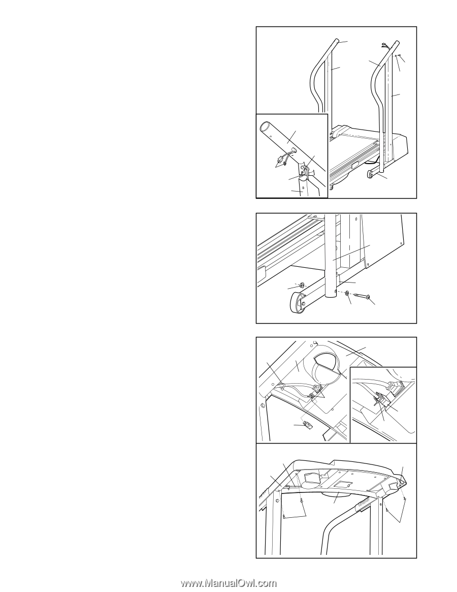
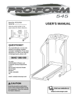
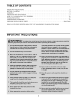
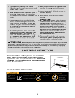
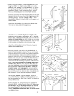
3. Refer to the inset drawing. If there is a plastic tie in the Cage Nut (70) in the Right Handrail (88), remove the plastic tie. Pull 15 cm (6 in.) of the two Wires (21) out of the right Upright (11). Feed the Wires up into the Right Handrail as shown. Using needlenose pliers, pull the Wires out of the indicated hole in the Right Handrail. Insert the bracket on the Right Handrail (88) into the right Upright (11), with the lower end of the Right Handrail beside the Extension Leg (34). Loosely thread a Short Handrail Bolt (89) with a Washer (39) into the upper end of the Upright. Attach the Left Handrail (1) as described above. Note: There are no wires in the left Upright (11). 3 1 88 11 88 70 21 Tie 11 89 39 11 34 4. Attach the lower end of the Right Handrail (88) to the Extension Leg (34) with a Handrail Bolt (91), a Handrail Washer (92), and a Handrail Nut (93) as shown. Do not tighten the Handrail Nut yet. Note: It may be necessary to push on the lower end of the Handrail to align the hole in the Handrail with the hole in the Extension Leg. Attach the Left Handrail to the left Extension Leg (not shown) as described above. 5. Place the Console Base (46) on the Handrails (88, 1) (only the Right Handrail is shown). Pull out just enough of the two Wires (21) to connect them to the receptacles in the Console Base. Make a loop with the indicated plastic tie and insert the end through the tie holder on the bottom of the Console Base. Locate the Wire that has a two-pin connector and a three-pin connector. Plug the connectors into the matching receptacles in the Console Base. If the connectors do not fit easily, rotate them and then plug them in. Next, plug the other Wire into the other receptacle on the Console Base. WARNING: Do not connect or disconnect the Wires whilst the treadmill power cord is plugged in. Securely tighten the plastic tie to prevent the Wires from slipping. Cut off the end of the plastic tie. Slide the Wire Cover (106) onto the connectors so that they are completely covered. See the inset drawing. Loop the included plastic tie around the Wire Cover (106) so that the plastic tie is in the two notches in the Wire Cover. Tighten the plastic tie and cut off the end. Refer to drawing 5b. Thread four Screws (79) into the Handrails (88, 1) and the Console Base (46). Make sure that the Wires (21) in the Right Handrail are clear of the screw holes. After all four Screws have been started, tighten the Screws until they are snug; do not overtighten them. 6 4 88 34 93 92 91 5a Tie 88 21 106 5b 21 88 46 106 Tie 1 46 79 79
-
 1
1 -
 2
2 -
 3
3 -
 4
4 -
 5
5 -
 6
6 -
 7
7 -
 8
8 -
 9
9 -
 10
10 -
 11
11 -
 12
12 -
13
-
14
-
15
-
16
-
17
-
18
-
19
 |
 |