ProForm 585tl English Manual - Page 5
Assembly
 |
View all ProForm 585tl manuals
Add to My Manuals
Save this manual to your list of manuals |
Page 5 highlights
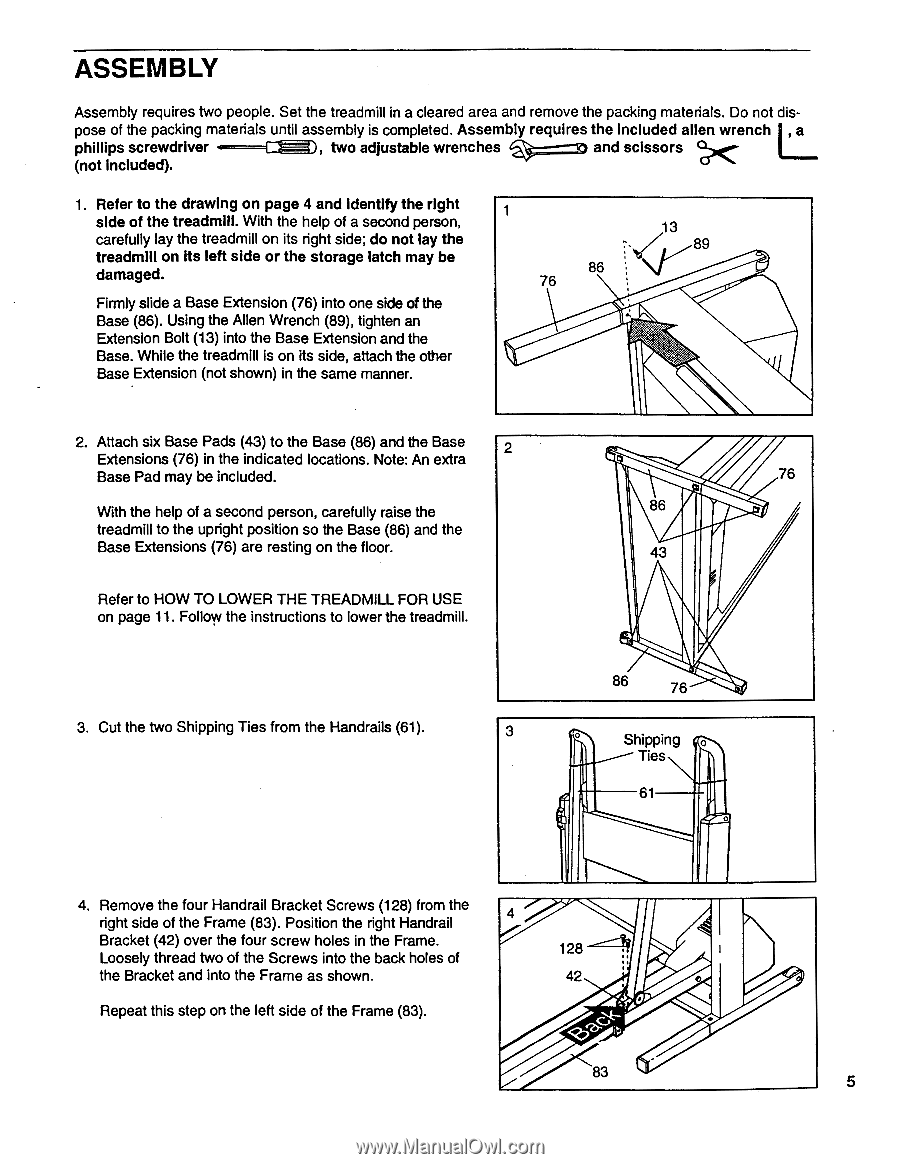
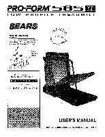
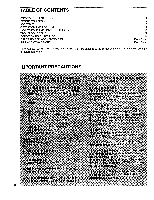
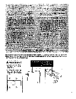
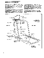
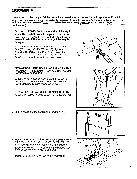
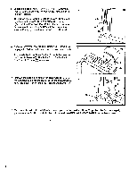
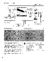
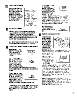
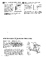
ASSEMBLY Assembly requires two people. Set the treadmill in a cleared area and remove the packing materials. Do not dis- pose of the packing materials until assembly is completed. Assembly requires the included alien wrench , a phillips screwdriver 4=-1 (not included). ), two adjustable wrenches i===x) and scissors X. 1. Refer to the drawing on page 4 and identify the right side of the treadmill. With the help of a second person, carefully lay the treadmill on its right side; do not lay the treadmill on its left side or the storage latch may be damaged. Firmly slide a Base Extension (76) into one side of the Base (86). Using the Allen Wrench (89), tighten an Extension Bolt (13) into the Base Extension and the Base. While the treadmill is on its side, attach the other Base Extension (not shown) in the same manner. 1 76 13 ••,/ 89 86 2. Attach six Base Pads (43) to the Base (86) and the Base 2 Extensions (76) in the indicated locations. Note: An extra Base Pad may be included. With the help of a second person, carefully raise the treadmill to the upright position so the Base (86) and the Base Extensions (76) are resting on the floor. Refer to HOW TO LOWER THE TREADMILL FOR USE on page 11. Follow the instructions to lower the treadmill. 76 86 43 3. Cut the two Shipping Ties from the Handrails (61). 86 76 3 O Shipping Ties 61 4. Remove the four Handrail Bracket Screws (128) from the right side of the Frame (83). Position the right Handrail 4 Bracket (42) over the four screw holes in the Frame. Loosely thread two of the Screws into the back holes of 128 the Bracket and into the Frame as shown. 42 Repeat this step on the left side of the Frame (83). 5
-
 1
1 -
 2
2 -
 3
3 -
 4
4 -
 5
5 -
 6
6 -
 7
7 -
 8
8 -
 9
9 -
 10
10 -
 11
11 -
12
-
13
-
14
-
15
-
16
-
17
-
18
-
19
 |
 |