ProForm 622 Exp Owners Manual - Page 6
Assembly
 |
View all ProForm 622 Exp manuals
Add to My Manuals
Save this manual to your list of manuals |
Page 6 highlights
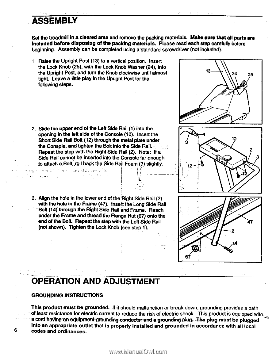
ASSEMBLY Set the treadmill in a cleared area and remove the packing materials. Make sure that all parts are included before disposing of the packing materials. Please read each step carefully before beginning. Assembly can be completed using a standard screwdriver (not included). 1. Raise the Upright Post (13) to a vertical position. Insert the Lock Knob (25), with the Lock Knob Washer (24), into the Upright Post, and turn the Knob clockwise until almost tight. Leave a little play in the Upright Post for the following steps. 13 24 25 2. Slide the upper end of the Left Side Rail (1) into the opening in the left side of the Console (10). Insert the Short Side Rail Bolt (12) through the metal plate under the Console, and tighten the Boit into the Side Rail.. .=: 3 Repeat the step with the Right Side Rail (2). Note: If a Side Rail cannot be inserted into the Console,far enough to attach a Bolt, coil back tbe Side Rail Foam (3) slightly. • _12 10 2 3 3. Align the hole in the lower end of the Right Side Rail (2) with the hole in the Frame (47). Inseit the Long Side Rail Bolt (14) through the Right Side Rail and Frame. Reach under the Frame and thread the Flange Nut (67) onto the end of the Bolt. Repeat the step with the Left Side Rail (not shown). Tighten the Lock Knob (see step 1). eot 67 47 2 4 OPERATION AND ADJUSTMENT GROUNDING INSTRUCTIONS This product must be grounded. If it should malfunction or break down, grounding provides a path of least resistance for electric current to reduce the risk of electric shock. This product is equipped withti: a cord.havinglan equipment-grounding conductorand a grounding plug: The plug must be plugged into an appropriate outlet that is properly installed and grounded in accordance with all local 6 codes and ordinances.
-
 1
1 -
 2
2 -
 3
3 -
 4
4 -
 5
5 -
 6
6 -
 7
7 -
 8
8 -
 9
9 -
 10
10 -
 11
11 -
 12
12 -
13
-
14
-
15
-
16
 |
 |