ProForm 622 Exp Owners Manual - Page 7
Danger
 |
View all ProForm 622 Exp manuals
Add to My Manuals
Save this manual to your list of manuals |
Page 7 highlights
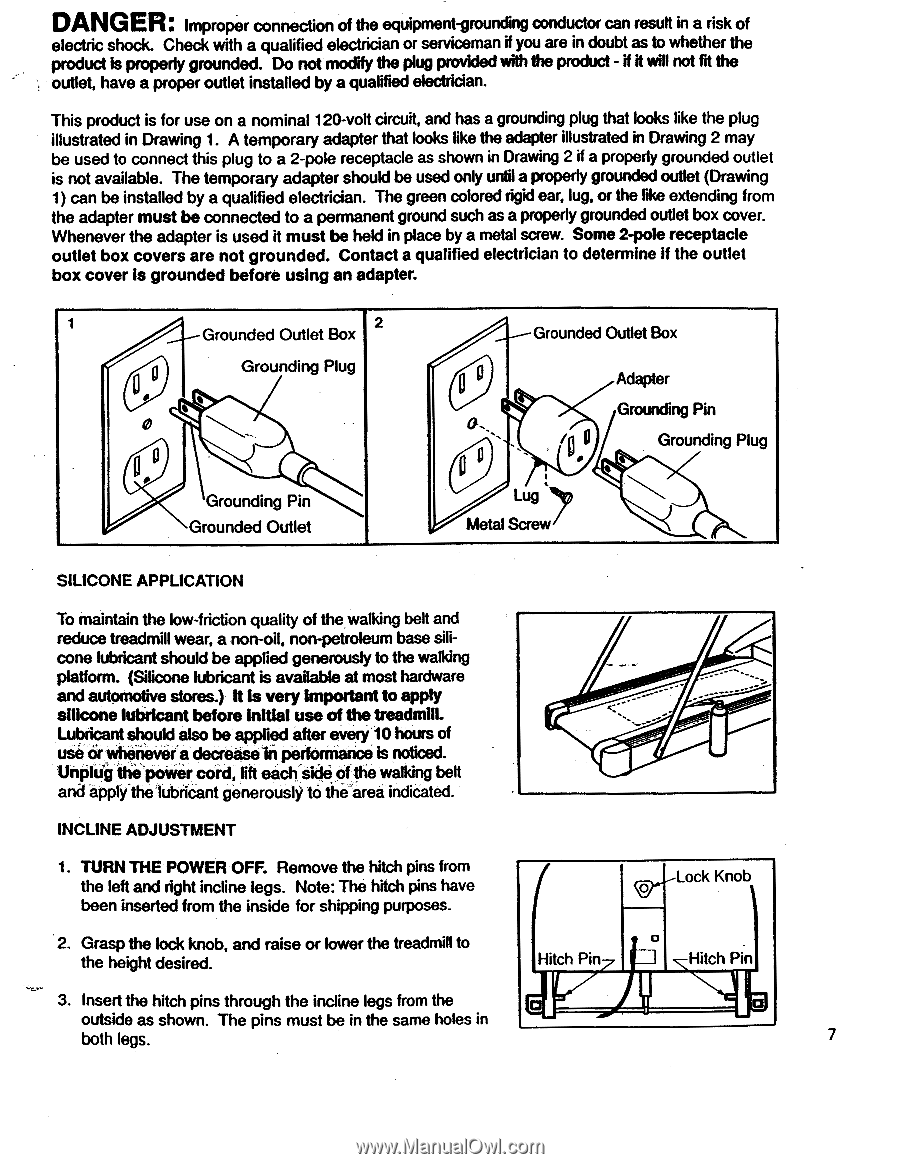
DANGER: Improper connection of the equipment-grounding conductor can result in a risk of electric shock. Check with a qualified electrician or serviceman if you are in doubt as to whether the product is properly grounded. Do not modify the plug provided with the product - if it will not fit the outlet, have a proper outlet installed by a qualified electrician. This product is for use on a nominal 120-volt circuit, and has a grounding plug that looks like the plug illustrated in Drawing 1. A temporary adapter that looks like the adapter illustrated in Drawing 2 may be used to connect this plug to a 2-pole receptacle as shown in Drawing 2 if a properly grounded outlet is not available. The temporary adapter should be used only until a properly grounded outlet (Drawing 1) can be installed by a qualified electrician. The green colored rigid ear, lug, or the like extending from the adapter must be connected to a permanent ground such as a properly grounded outlet box cover. Whenever the adapter is used it must be held in place by a metal screw. Some 2-pole receptacle outlet box covers are not grounded. Contact a qualified electrician to determine if the outlet box cover is grounded before using an adapter. 1 2 Grounded Outlet Box Grounding Plug 0 • g Grounding Pin Grounded Outlet Grounded Outlet Box QO Lug Metal Screw Adapter Grounding Pin Grounding Plug SILICONE APPLICATION To maintain the low-friction quality of the walking belt and reduce treadmill wear, a non-oil, non-petroleum base silicone lubricant should be applied generously to the walking platform. (Silicone lubricant is available at most hardware and automotive stores.) it is very important to apply silicone lubricant before initial use of the treadmill. Lubricant should also be applied after every 10 hours of use or whenever a decrease performance is noticed. Unplug thiipower cord, lift eachside of the walking belt and apply'the lubricant generously to the area indicated. INCLINE ADJUSTMENT 1. TURN THE POWER OFF. Remove the hitch pins from the left and right incline legs. Note: The hitch pins have been inserted from the inside for shipping purposes. 2. Grasp the lock knob, and raise or lower the treadmill to the height desired. 0 Lock Knob Hitch Pin 0 Hitch Pin 3. Insert the hitch pins through the incline legs from the outside as shown. The pins must be in the same holes in both legs. 7
-
 1
1 -
 2
2 -
 3
3 -
 4
4 -
 5
5 -
 6
6 -
 7
7 -
 8
8 -
 9
9 -
 10
10 -
 11
11 -
 12
12 -
13
-
14
-
15
-
16
 |
 |