ProForm 650 Crosstrainer Treadmill English Manual - Page 8
If The Connectors Are Not Con
 |
View all ProForm 650 Crosstrainer Treadmill manuals
Add to My Manuals
Save this manual to your list of manuals |
Page 8 highlights
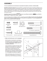
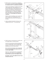
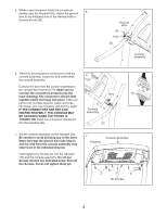
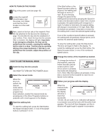
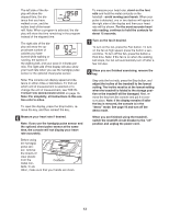
5. While a second person holds the console assembly near the Handrail (20), attach the ground 5 wire to the indicated hole in the Handrail with a Ground Screw (33). Ground Wire 33 Hole 20 Console Assembly 6. While the second person continues to hold the console assembly, locate the wire underneath 6 the console assembly. Connect the wire from the console assembly to the Upright Wire Harness (77). Make sure to connect the connectors properly (see the inset drawing). The connectors should slide Wire 77 together easily and snap into place. If the con- nectors do not slide together easily and snap into place, turn one connector and then try again. IF THE CONNECTORS ARE NOT CONNECTED PROPERLY, THE CONSOLE MAY Console 77 Assembly BE DAMAGED WHEN THE POWER IS TURNED ON. Insert the connectors downward into the Handrail (20). 20 7. Set the console assembly on the Handrail (20). Be careful to avoid pinching any of the wires. Make sure that the ground wire (see step 5) and the wire from the console assembly (see step 6) are in the indicated channel. Hand tighten five Screws (3) into the Handrail (20) and the console assembly. Do not put Screws into the two indicated holes. Start all five Screws, but do not tighten them yet. 7 Channel Console Assembly 20 3 3 3 No Screws 8
-
 1
1 -
2
-
 3
3 -
 4
4 -
 5
5 -
 6
6 -
 7
7 -
 8
8 -
 9
9 -
 10
10 -
 11
11 -
 12
12 -
 13
13 -
14
-
15
-
16
-
17
-
18
-
19
-
20
-
21
-
22
-
23
-
24
-
25
-
26
-
27
-
28
 |
 |
