ProForm 7.5c Owners Manual - Page 8
Trouble, Shooting, Maintenance
 |
View all ProForm 7.5c manuals
Add to My Manuals
Save this manual to your list of manuals |
Page 8 highlights
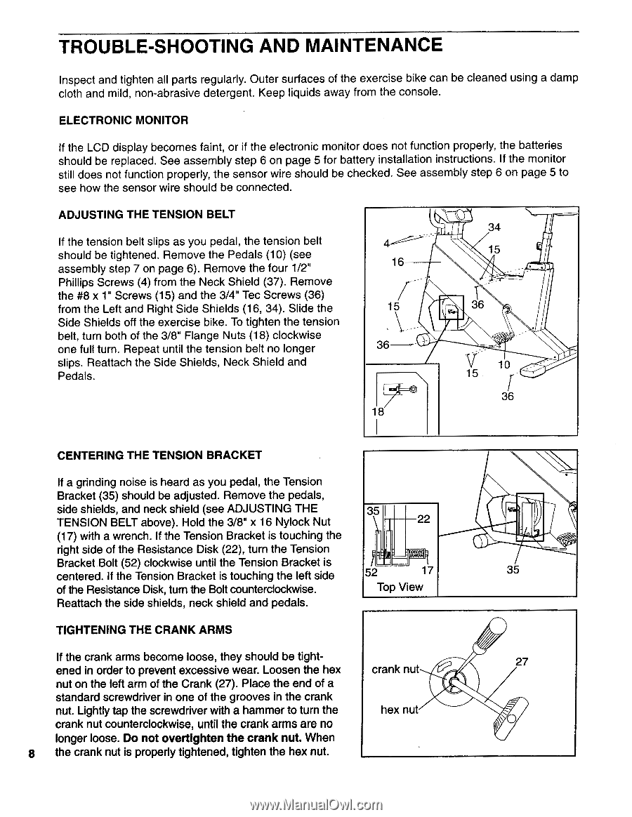
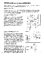
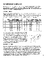
TROUBLE-SHOOTING AND MAINTENANCE Inspect and tighten all parts regularly. Outer surfaces of the exercise bike can be cleaned using a damp cloth and mild, non-abrasive detergent. Keep liquids away from the console. ELECTRONIC MONITOR If the LCD display becomes faint, or if the electronic monitor does not function properly, the batteries should be replaced. See assembly step 6 on page 5 for battery installation instructions. If the monitor still does not function properly, the sensor wire should be checked. See assembly step 6 on page 5 to see how the sensor wire should be connected. ADJUSTING THE TENSION BELT If the tension belt slips as you pedal, the tension belt should be tightened. Remove the Pedals (10) (see assembly step 7 on page 6). Remove the four 1/2" Phillips Screws (4) from the Neck Shield (37). Remove the #8 x 1" Screws (15) and the 3/4" Tec Screws (36) from the Left and Right Side Shields (16, 34). Slide the Side Shields off the exercise bike. To tighten the tension belt, turn both of the 3/8" Flange Nuts (18) clockwise one full turn. Repeat until the tension belt no longer slips. Reattach the Side Shields, Neck Shield and Pedals. 16 15 36 18 34 15 36 V 10 15 36 CENTERING THE TENSION BRACKET If a grinding noise is heard as you pedal, the Tension Bracket (35) should be adjusted. Remove the pedals, side shields, and neck shield (see ADJUSTING THE 35 TENSION BELT above). Hold the 3/8" x 16 Nylock Nut 22 (17) with a wrench. If the Tension Bracket is touching the right side of the Resistance Disk (22), turn the Tension Bracket.Bolt (52) clockwise until the Tension Bracket is centered. If the Tension Bracket is touching the left side 52 17 35 of the Resistance Disk, turn the Bolt counterclockwise. Top View Reattach the side shields, neck shield and pedals. TIGHTENING THE CRANK ARMS If the crank arms become loose, they should be tightened in order to prevent excessive wear. Loosen the hex crank nut 27 nut on the left arm of the Crank (27). Place the end of a standard screwdriver in one of the grooves in the crank nut. Lightly tap the screwdriver with a hammer to turn the hex nut crank nut counterclockwise, until the crank arms are no longer loose. Do not overtighten the crank nut. When 8 the crank nut is properly tightened, tighten the hex nut.
-
 1
1 -
2
-
 3
3 -
 4
4 -
 5
5 -
 6
6 -
 7
7 -
 8
8 -
 9
9 -
 10
10 -
 11
11 -
 12
12
 |
 |