ProForm 775s English Manual - Page 5
four M8 Split Washers 41 and four M8 Nylon - console
 |
View all ProForm 775s manuals
Add to My Manuals
Save this manual to your list of manuals |
Page 5 highlights
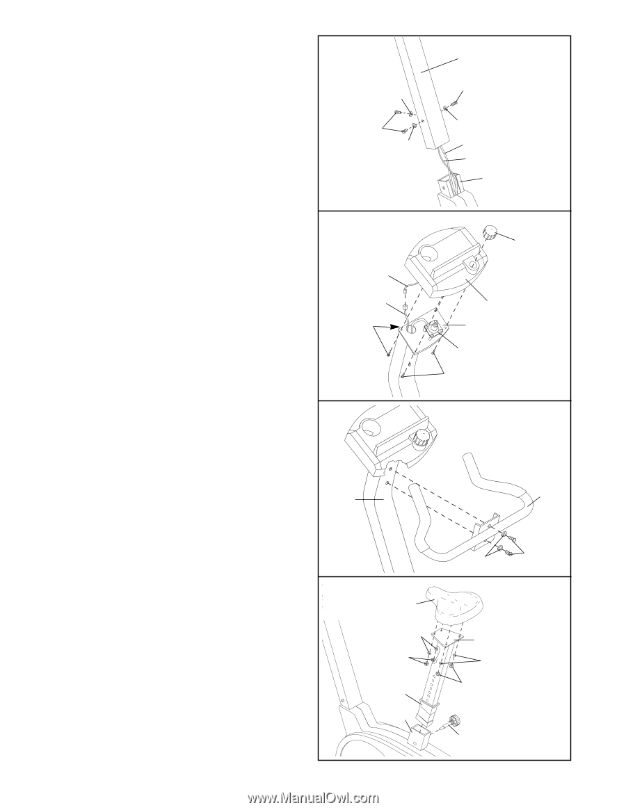
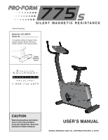
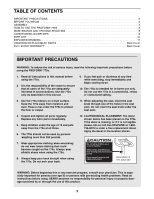
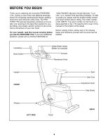
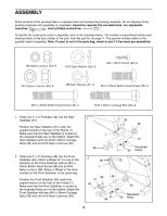
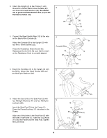
3. Attach the Upright (2) to the Frame (1) with three M10 x 25mm Button Head Screws (25) 3 and three M10 Split Washers (26). Be careful not to pinch the Reed Switch Wire (13) or the Resistance Cable (10). 26 25 26 4. Connect the Reed Switch Wire (13) to the wire on the back of the Console (8). Attach the Console (8) to the Upright (2) with four M4 x 16mm Screws (22). Press the Resistance Knob (9) onto the Resistance Control (10). Be sure that the mark on the Resistance Knob is correctly aligned. 4 Console Wire 13 22 5. Attach the Handlebar (4) to the Upright (2) with 5 two M10 x 25mm Hex Head Screws (25) and two M10 Split Washers (26). 2 25 26 10 13 1 9 8 2 10 22 2 4 6. Attach the Seat (16) to the Seat Post (3) with four M8 Split Washers (41) and four M8 Nylon 6 Locknuts (20). Insert the Seat Post (3) into the Frame (1). Press the Frame Bushing (17) into place in the Frame. Align one of the holes in the Seat Post (3) with the hole in the Frame (1). Insert the Lock Knob (14) into the Frame and the Seat Post. Tighten the Lock Knob. 5 26 25 16 41 20 17 1 3 41 20 14
-
 1
1 -
 2
2 -
 3
3 -
 4
4 -
 5
5 -
 6
6 -
 7
7 -
 8
8 -
 9
9 -
 10
10 -
 11
11 -
12
 |
 |