ProForm 775s English Manual - Page 8
Maintenance And Trouble-shooting - exercise bike parts
 |
View all ProForm 775s manuals
Add to My Manuals
Save this manual to your list of manuals |
Page 8 highlights
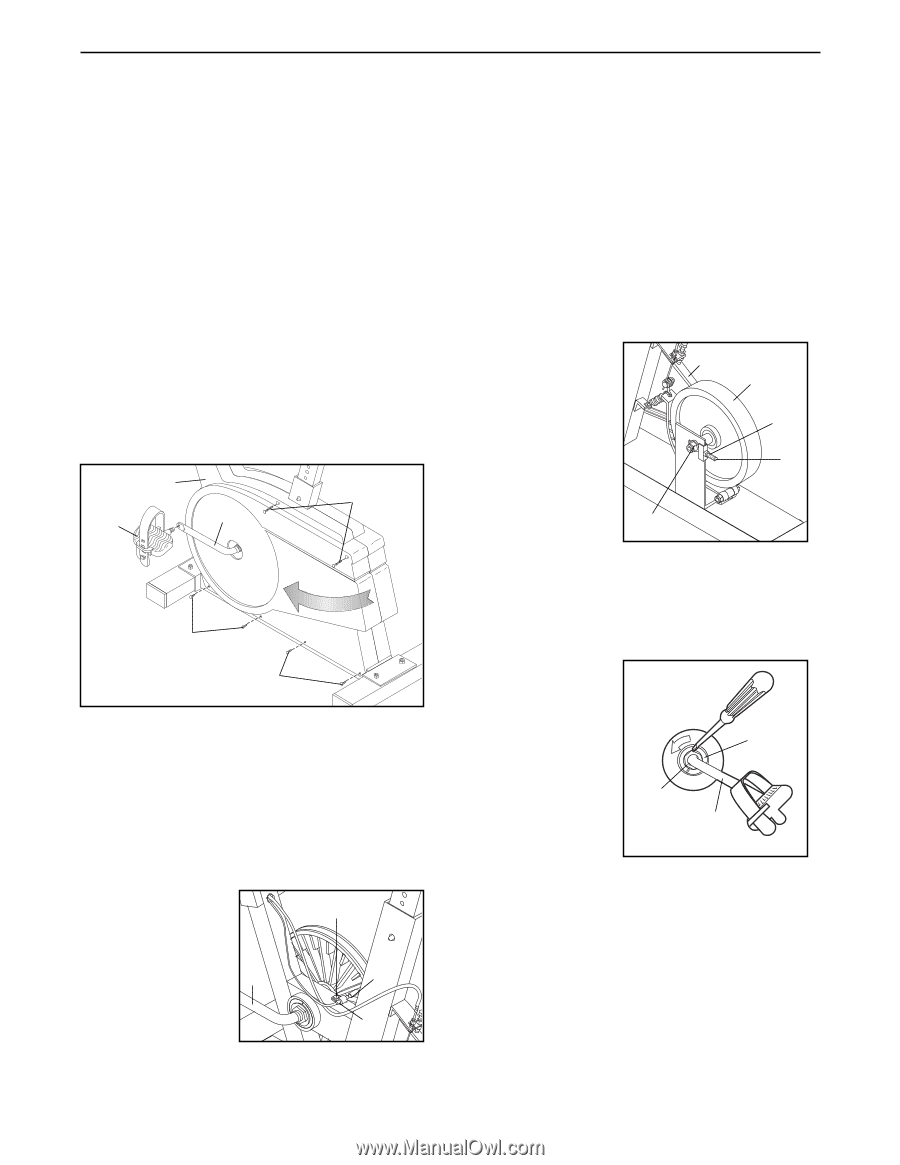
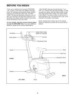
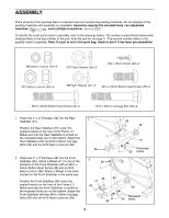
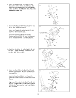
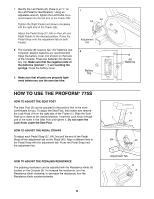
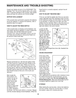
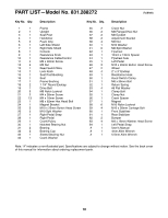
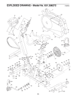
MAINTENANCE AND TROUBLE-SHOOTING Inspect and tighten all parts of the PROFORM¨ 775s regularly. The 775s can be cleaned with a soft, damp cloth. To prevent damage to the console, keep liquids away and keep the console out of direct sunlight. Reed Switch is correctly adjusted, reattach the left side shield. HOW TO ADJUST THE DRIVE BELT BATTERY REPLACEMENT If the console does not function properly, the batteries should be replaced. To replace the batteries, refer to assembly step 8 on page 6. HOW TO ADJUST THE REED SWITCH If the you can feel the pedals slip when you are exercising, especially when the resistance knob is turned to the maximum setting, the Drive Belt (19) may need to be adjusted. To adjust the Drive Belt, both side shields must be removed. Refer to the instructions at the left to remove the left side shield. Remove the right side shield in the same manner. If the console does not display correct feedback, the reed switch should be adjusted. In order to adjust the reed switch, the Left Side Shield (6) must be removed. First, using an adjustable wrench, turn the Left Pedal (45) clockwise to remove the Pedal from the left arm of the Crank (29). 6 21 45 29 Loosen the M8 Flanged Hex Nut (36) on each side of 19 42 the Flywheel (42). Tighten the M6 Nut 39 (39) on each M6 Eyebolt (37) until the 37 Drive Belt (19) is tight. Be sure that you tighten each M6 Nut an equal 36 amount. Once the Drive Belt is tight, tighten the M8 Flanged Hex Nuts (36). Reattach the side shields. 22 CRANK ADJUSTMENT 22 Remove all Screws (21, 22) from the bottom of the Left Side Shield (6). Grasp both Side Shields at the top and gently pull them apart. Make sure that the arm of the Crank (29) is in the position shown in the drawing above. Hold the Left Side Shield at the rear and pull it gently away from the frame. Work the Left Side Shield forward off the arm of the Crank and remove it. Next, locate the Reed Switch (13). 22 Loosen, but do not remove, the M4 x 16mm Screw (22). Slide the Reed 29 57 Switch slightly toward or away from 13 the Magnet (57) on the pulley. Retighten the Screw. Turn the Crank (29) for a moment. Repeat until the console displays correct feedback. When the If the arms of the Crank (29) become loose, they should be tightened in order to prevent excessive 33 wear. Loosen the Crank Nut (35) on the left arm of the Crank. Place the end of a standard 35 29 screwdriver in one of the slots in the Slotted Bearing Nut (33). Lightly tap the screwdriver with a hammer to turn the Slotted Bearing Nut counterclockwise until the arms are no longer loose. Do not overtighten the Slotted Bearing Nut. When the Slotted Bearing Nut is properly tightened, tighten the Crank Nut. STORAGE When storing the exercise bike, remove the batteries from the console. Keep the exercise bike in a clean, dry location, away from moisture and dust. 8
-
 1
1 -
2
-
 3
3 -
 4
4 -
 5
5 -
 6
6 -
 7
7 -
 8
8 -
 9
9 -
 10
10 -
 11
11 -
 12
12
 |
 |