ProForm 8.4s English Manual - Page 4
overtighten
 |
View all ProForm 8.4s manuals
Add to My Manuals
Save this manual to your list of manuals |
Page 4 highlights
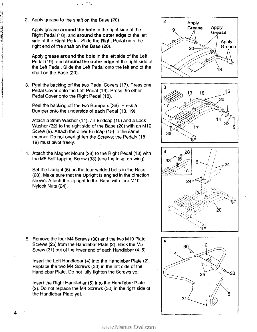
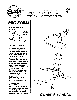
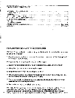
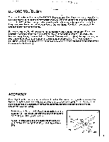
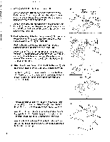
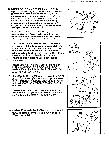
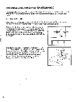
2. Apply grease to the shaft on the Base (20). Apply grease around the hole in the right side of the Right Pedal (18), and around the outer edge of the left side of the Right Pedal. Slide the Right Pedal onto the right end of the shaft on the Base (20). Apply grease around the hole in the left side of the Left Pedal (19), and around the outer edge of the right side of the Left Pedal. Slide the Left Pedal onto the left end of the shaft on the Base (20). 3.• Peel the backing off the two Pedal Covers (17). Press one Pedal Cover onto the Left Pedal (19). Press the other Pedal Cover onto the Right Pedal (18). Peel the backing off the two Bumpers (36). Press a Bumper onto the underside of each Pedal (18, 19). Attach a 2mm Washer (14), an Endcap (15) and a Lock Washer (32) to the right side of the Base (20) with an M10 Screw (9). Attach the other Endcap (15) in the same manner. Do not overtighten the Screws; the Pedals (18, 19) must pivot freely. 4. Attach the Magnet Mount (28) to the Right Pedal (18) with the M5 Self-tapping Screw (33) (see the inset drawing). Set the Upright (6) on the four welded bolts in the Base (20). Make sure that the Upright is angled in the direction shown. Attach the Upright to the Base with four M10 Nylock Nuts (24). 2 19 Apply Grease 20 Apply Grease Apply Grease 18 3 19 18 15 20 17 14 32 17 9 36 4 28 33 6 s 24 r, 24 is 20 5. Remove the four M4 Screws (30) and the two M10 Plate Screws (25) from the Handlebar Plate (2). Back the M5 Screw (31) out of the lower end of each Handlebar (4, 5). 5 30 4 2 Insert the Left Handlebar (4) into the Handlebar Plate (2). .4>.0•'• • Replace the two M4 Screws (30) in the left side of the Handlebar Plate. Do not fully tighten the Screws yet. 25 30 Inserrthe Right Handlebar (5) into the Handlebar Plate. (2). Do not replace the M4 Screws (30) in the right side of the Handlebar Plate yet. 5 31 4
-
 1
1 -
 2
2 -
 3
3 -
 4
4 -
 5
5 -
 6
6 -
 7
7 -
 8
8 -
 9
9 -
 10
10 -
11
-
12
 |
 |