ProForm 800 English Manual - Page 8
end of the Long Pad Tube 8. Insert the Long
 |
View all ProForm 800 manuals
Add to My Manuals
Save this manual to your list of manuals |
Page 8 highlights
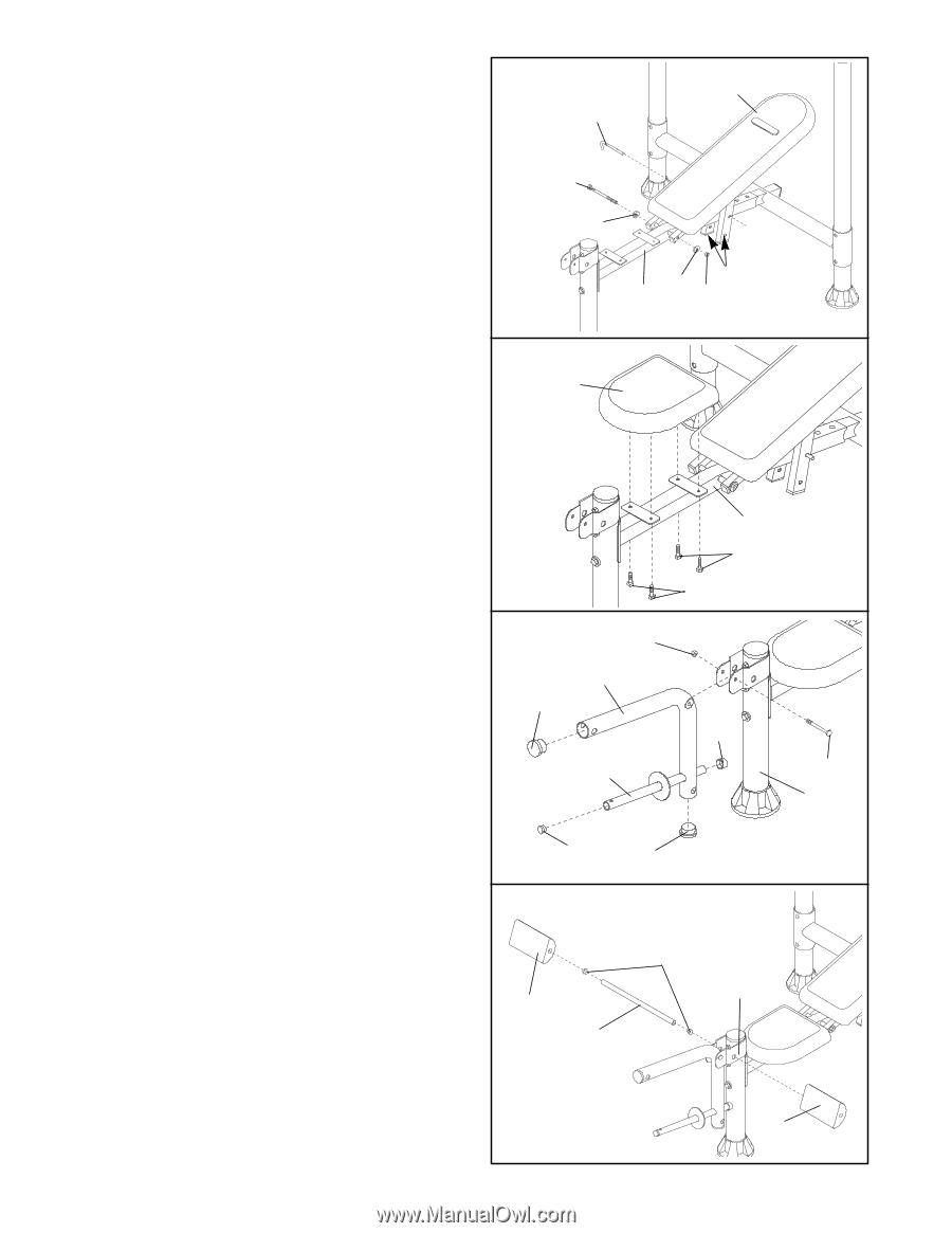
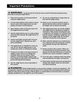
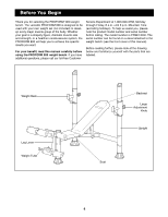
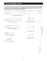
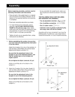
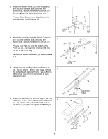
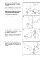
7. Lubricate the M10 x 180mm Bolt (28). Attach the Backrest (12) to the Bench Frame (5) with the Bolt, two M10 Washers (6), and an M10 Nylon Locknut (11). Secure the Backrest (12) to the Bench Frame (5) by inserting the Locking Pin (27) through one of the three sets of holes in the adjustment tubes and the tube (not shown) on the Bench Frame. Make sure the Locking Pin (27) is completely inserted through both adjustment tubes. Tighten the Bolts (9) used in step 6. 8. Attach the Seat (17) to the Bench Frame (5) with four M6 x 16mm Bolts (26) 7 12 27 28 6 5 6 11 Adjustment Tubes 8 17 5 26 26 9. Tap two 50mm Round Inner Caps (25) into the ends of the Leg Lever (7). Insert a 25mm Round Inner Cap (36) into the end of the weight tube on the Leg Lever. Place a 25mm Angle Cap (35) on the other end of the weight tube. 9 25 11 7 Attach the Leg Lever (7) to the Front Leg (3) with an M10 x 70mm Bolt (32) and an M10 Nylon Locknut (11). Weight Tube 35 32 3 36 25 10. Place a 19mm Round Inner Cap (33) into each 10 end of the Long Pad Tube (8). Insert the Long Pad Tube through the holes in the Front Leg (3). Slide a Leg Pad (22) onto each side of the Long Pad Tube. 22 8 33 3 22 8
-
 1
1 -
2
-
 3
3 -
 4
4 -
 5
5 -
 6
6 -
 7
7 -
 8
8 -
 9
9 -
 10
10 -
 11
11 -
 12
12 -
 13
13 -
14
-
15
-
16
-
17
-
18
-
19
 |
 |