ProForm C70 Owners Manual - Page 5
Model, Pfc70, Adjustment
 |
View all ProForm C70 manuals
Add to My Manuals
Save this manual to your list of manuals |
Page 5 highlights
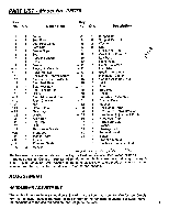
PART LIST - Model No. PFC70 Key No. Qty. Description Key No. Qty. Description ' -1 1 Frame 2 1 Seat Post 33 1 Support Bar 34 8 Support Bar Bolt 3 1 Seat Post Guide 35 2 Washer 4 3 Seat Nut 36 2 Nut 5 2 Fascia Clips 37 1 Left Crank Arm 6 1 Seat 7 1 Rubber Bellows 38 2 Crank Arm Cover 39 1 Left Pedal 8 1 Body 40 1 Right Pedal -9 1 Fascia - 41 2 Crank Pin w/Nut -10 1 Electronic Console 42 1 Handlebar - 11 1 Pulse Monitor 43 2 Bearing Assembly 12 3 Resistance Control Screw 44 1 Handlebar Clamp 13 1 Resistance Knob w/Cable 14 1 Seat Post Base 45 4 Bearing Assembly Nut 46 2 C-Clip 15 4 Seat Post Bolt 47 1 Axle 16 1 Seat Locking Pin 48 1 Sprocket 17 1 Collar 49 1 Chain -18 1 Seat Adjustment Knob 50 2 Freewheel Assembly 19 1 Right Crank Arm - 51 2 Bracket Bolts 20 1 Nut 52 1 Magnet -a- 21 2 Crank Plate 53 1 Resistance Strap .--22 1 Rear Leg 54 1 Resistance Cable Bracket 23 4 Washer 24 4 Allen Bolt -55 56 1 Handlebar Adjustment Knob 2 Handlebar Cap 25 4 Leg Cap - 57 2 Handlebar Bolt 26 27 ..28 1 Bolt 1 Resistance Buckle 1 Front Leg 58 2 Washer 59 1 Carriage Bolt 60 2 Foam Handgrip 29 1 Monitor Wire 61 1 Spacer 30 1 Flywheel 31 1 Flywheel Shaft 1 Owner's Manual 1 Electronic Console Guide 32 2 Spacer /1-4 1 ."4/4; (et6 Replacement parts can be ordered by calling our Customer Service Department toll-free at 1-800-999-3756, (in Canada 1-800-824-8949), during regular business hours: Monday - Friday, 6 a.m. - 6 p.m., Mountain Time. When ordering parts, please refer to the product name and model number, and the key number and description of the part needed. ADJUSTMENT HANDLEBAR ADJUSTMENT The angle of the handlebars should be adjusted to a position that is comfortable for you. Simply turn the handlebar adjustment knob (located in front of the handlebars) counterclockwise, move the handlebars to the desired position, and retighten the knob. 5
-
 1
1 -
 2
2 -
 3
3 -
 4
4 -
 5
5 -
 6
6 -
 7
7 -
 8
8
 |
 |
