ProForm Crosswalk 3.0 Xt Treadmill English Manual - Page 10
View from Above
 |
View all ProForm Crosswalk 3.0 Xt Treadmill manuals
Add to My Manuals
Save this manual to your list of manuals |
Page 10 highlights
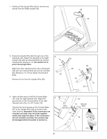
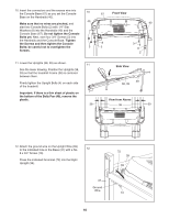
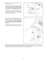
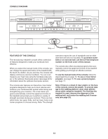
10. Insert the connectors and the excess wire into the Console Base (67) as you set the Console 10 Base on the Handrails (40). 40 Make sure that no wires are pinched, and start two Console Bolts (2) with 1/4" Star Washers (8) into the Handrails (40) and the Console Base (67). Do not tighten the Console Bolts yet. Next, start four 3/4" Screws (3) into the Handrails and the Console Base. Tighten the Screws and then tighten the Console Bolts; be careful not to overtighten the 3 Screws. 67 Front View 40 8 3 2 8 2 11. Lower the Uprights (38, 39) as shown. See the lower drawing. Position the Uprights (38, 39) so that the treadmill Frame (36) is centered between them. Firmly tighten the Upright Bolts (4) on each side of the treadmill. Important: If there is a thin sheet of plastic on the bottom of the Belly Pan (49), remove the plastic. 11 38 Side View 4 49 38, 39 View from Above 36 39 12. Attach the ground wire on the Upright Wire (69) to the indicated hole in the Base (37) with a No. 12 8 x 3/4" Screw (10). Press the indicated Grommet (72) into the Right Upright (39). 37 Ground Wire 72 39 69 10 10
-
 1
1 -
2
-
3
-
4
-
 5
5 -
 6
6 -
 7
7 -
 8
8 -
 9
9 -
 10
10 -
 11
11 -
 12
12 -
 13
13 -
 14
14 -
 15
15 -
16
-
17
-
18
-
19
-
20
-
21
-
22
-
23
-
24
-
25
-
26
-
27
-
28
-
29
-
30
-
31
-
32
 |
 |
