Pyle PCT60 User Guide - Page 2
Move the On switch to Cable Tester.
 |
View all Pyle PCT60 manuals
Add to My Manuals
Save this manual to your list of manuals |
Page 2 highlights
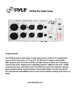
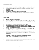
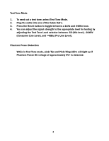
Installing the battery 1. Locate the small screw for the battery cover plate on the back of the unit 2. Using a small Phillips head screwdriver, rotate the small screw counter clockwise. 3. Remove the plate. 4. Insert the two AA batteries with the correct polarity. 5. Reattach battery cover plate, insert screw and turn clockwise to tighten. Testing cables 1. Move the On switch to Cable Tester. 2. To test pins 1-3, you may adjust the Switch 1-3 selector to SW1. For cables with more than three pins, you may adjust the selector to SW2 for pins 4-6 and SW3 for pins 7-8. 3. Insert one end of the cable into one of the various inputs. 4. Insert the other end of the cable into one of the various outputs. 5. If the Grounded Shield LED lights up, this indicates that the XLR out shield has been connected to pin1/sleeve. 6. Once the cable has been connected to both an input and output, the LED grid will light up to show which pins are connected. 7. Each LED shows which input pins are connected to each output pin. The Input pins are represented vertically while the output pins are represented horizontally. Ex. The LED in the top right hand corner shows that Pin1/Sleeve on the input is going to Pin1/Sleeve on the output side. 8. For cables with more than three pins, you may adjust the Switch 1-3 selec tor to SW2 for pins 4-6 and SW3 for pins 7-8. 2
-
 1
1 -
 2
2 -
 3
3 -
 4
4
 |
 |