Pyle PEXA8000 PEXA3000 Manual 1 - Page 4
Graphic LCD Display Screen Explain, Front Panel - pro amp
 |
View all Pyle PEXA8000 manuals
Add to My Manuals
Save this manual to your list of manuals |
Page 4 highlights
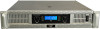
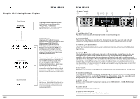
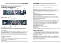
Graphic LCD Display Screen Explain PEXA SERIES First Screen PYLE PRO Opening Screen: On power-up,the LCD Control Screen displays the "PYLE PRO...".After a few seconds,then the "Second Interface"Working Status screen appears. Second Screen Third Screen Fourth Screen And then display: displays Left and Right channel outputs POWR(0W), displays Left and Right channel CLIP(ON/OFF), displays Left and Right channel PROT(ON/OFF),displays Left and Right channel heat sinkTEMP(oC) and displays left and right channel output level meters, you can view the values of the output signal and view how many power output. If stereo/bridge switch or limiter switch or potentiometer action, and then you can view this screen, you can view stereo/bridge working mode and limiter switch set position ,and shows left and right channel output attenuation histogram, and read the value of the output attenuation,output attenuation range from - to 0dB.After a few seconds return to second screen . Press 4/8 tact switch ,you can view this screen, after a few seconds return to second screen.If you select 8 the output power value is 8 ,else show output power is 4 . Page 6 PEXA SERIES Front Panel 1 2 3 45 6 7 8 9 10 1.Rack Mounting Ears Two front-panel mounting holes are provided on each mounting ear. 2.Fan Outlet Grill PEXA Series amplifiers are cooled by fan.Cool air flows over the heat sink and exhausts through the front grill.Make sure this outlet remains clear to allow unrestricted airflow. 3.Channel Level attenuators Two input attenuators adjust level for their respective amplifier channels. In Bridged Mono modes, the channel A attenuator controls overall signal level (see rear panel mode switch description). 4.Protect LEDS This Red LED indicates that the amp channel is in Protect mode.During Power up, the amp briefly goes into protect mode in order to prevent any loud speakers from being fed the speakers. After a few seconds the amp comes out of protect mode and is ready for normal operation. If the amp stays in Protect mode, this indicates that there may be a problem internal to the amp. If the amp goes into Protect mode during operation this indicates that either a problem has developed internal to the amp or the amp is being over-stressed and needs to cool down. After a Protect condition, the amp must be reset by cycling the power off and then on again in order to continue using it. 5.CLIP LEDS: When the output power exceeds the safe working range of the amplifier,the CLIP LED are lit. 6.Graphic LCD display: LCD display as: Company name/logo, detailed power at 2ohm/4ohm/8ohm,Limiter,Working mode, Protection(L/R), Level(L/R), Temperature(L/R heatsink), Clip(L/R), Gain(L/R),Detail wiring diagram you can refer to Graphic LCD Display Screen Explain. 7.LEVEL LEDS SIGNAL LEDS inintensity inresponse to signals up to -30dB.-20dB to -10dB LEDS indicate output levels. 8.Power switch This switch turns the amp on and off. 9.Optional Rack Handles. Available from your authorized Crest Audio supplier. Page 3
-
 1
1 -
 2
2 -
 3
3 -
 4
4 -
 5
5
 |
 |
