Pyle PLUTV58BKA Instruction Manual - Page 2
Precautions, Wiring Instructions, Ground Connection, Remote Turn-on Connection, Speaker Connections
 |
View all Pyle PLUTV58BKA manuals
Add to My Manuals
Save this manual to your list of manuals |
Page 2 highlights
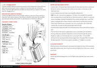
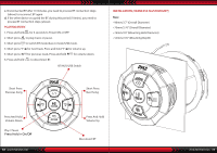
PRECAUTIONS • This unit is designed for negative ground 12-14.50 Volts (DC) operation only. • Use speakers with an impedance of 4 Ohms • Avoid installing the unit where: • It would be subject to high temperatures, such as from direct sunlight or hot air from the heater. • It would be exposed to rain or moisture. • It would be subject to dust or dirt. • If your vehicle or boat is parked in direct sunlight and there is a considerable rise in temperature inside the car, allow the unit to cool off before operation. • When installing the unit horizontally, be sure not to cover the heatsink fins with the floor carpet. • If this unit is placed too close to the resources radio, an interference may occur. In this case, separate the amplifier from the car radio. • This power amplifier employs a protection circuit to protect the transistors and speakers if the amplifier malfunctions. Do not attempt to test the protection circuits by covering the heatsink or connecting improper loads. • Do not use the unit with a weak auto battery as its optimum performance depends on a normal battery supply voltage. • For safety reasons, keep the volume of your audio system moderate so that you can still hear normal traffic sounds in a reasonable distance. WIRING INSTRUCTIONS POWER CONNECTION The battery terminal (BATT) must be connected directly to the positive terminal of the vehicle battery to provide an adequate voltage source and minimize noise. Connecting the battery terminal lead to any other point (such as the fuse block) will reduce the power output and may cause noise and distortion. Use only #12 gauge or thicker (smaller gauge #) wire for this lead and connect it to the terminal of the battery after all other wiring is completed. GROUND CONNECTION The ground terminal (GND) connection is also critical to the correct operation of the amplifier. Use a wire of the same gauge as the power connection (#8 or thicker) and connect it between the ground terminal (GND) of the amplifier and a metal part of the vehicle close to the mounting location. This wire should be as short as possible and any paint or rust at the grounding point should be scraped away to provide a clean metal surface to which the end of the ground wire can be screwed or bolted. 2 www.PyleUSA.com REMOTE TURN-ON CONNECTION The amplifier is turned on by applying +12V to the remote turn-on terminal (REM). The wire lead to this terminal should be connected to the "Auto-Antenna" lead from the vehicle/or boat stereo resources which will provide the +12V only when the stereo resources is turned on. If the car stereo does not provide an "Auto-Antenna" lead, the remote turn-on lead may be wired to an "Accessory" or "Radio" terminal in the vehicle's/or boat's fuse block. This will turn the amplifier on and off with the ignition key, regardless of whether the stereo resources is on or off. The remote turn-on lead does not carry large currents. So #16 gauge wire may be used for this application. SPEAKER CONNECTIONS Depending on the type and number of speakers used with the amplifier wire them to the speaker terminals as per the appropriate wiring diagram. For most applications #18 gauge wire should be used for the speaker leads but in no case thinner than #16 gauge. For leads is excess of 10 feet #12 gauge is recommended. When wiring the speakers, pay careful attention to the polarity of the terminals on the speakers and make certain they correspond to the polarity of the corresponding terminals on the amplifier. Do not ground any speaker leads to the chassis of the vehicle/or boat. OPERATION After the amplifier has been installed and all connections have been made carefully and securely, turn the radio on so that the amplifier is switched on automatically. After a short power-on period, the amplifier reaches its full performance. Now turn up the volume slowly using the volume control of the radio. If there is no sound or only a distorted replay, switch off the radio immediately - the amplifier will also switch off automatically - and check if all connections have been made correctly. GND (-) = GROUND CONNECTION Connect the GND terminal to the chassis ground of your vehicle/or boat and take care of best electric and mechanic contact. In doing so, drill a hole into the vehicle/or boat chassis near the amplifier then remove color, dirt or any other substance from the ground point. Thereafter fasten the cable end with added ring terminal by using a screw. Ensure that the ground connection is as short as possible and that the cable diameter is sufficient (min 4mm). Route the ground cables from the radio and all other equipment parts, like equalizer, active crossover network or other amplifiers, to the same ground point. www.PyleUSA.com 3
-
 1
1 -
 2
2 -
 3
3 -
 4
4 -
 5
5 -
 6
6 -
 7
7 -
 8
8
 |
 |
