Reebok 825 English Manual - Page 6
Frame Assembly
 |
View all Reebok 825 manuals
Add to My Manuals
Save this manual to your list of manuals |
Page 6 highlights
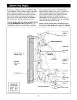
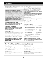
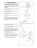
Frame Assembly 1 1. Before beginning assembly, make sure you have read and understood the information on page 5. Locate and open the parts bag labeled ÒFRAME ASSEMBLY.Ó Support Tube Press a 2Ó Square Inner Cap (33) into each open tube on the Press Frame (12). Press a 2Ó Square Inner Cap (33) into the support tube on the Main Upright (3). Press a 2Ó x 3Ó Inner Cap (24) into the open end of the Main Upright (3). 50 50 Press a 2Ó x 3Ó Inner Cap (24) into each end of the Stabilizer (5). Attach the Stabilizer (5) to the Main Upright (3) with two 3/8Ó x 3 3/4Ó Carriage Bolts (52) and two 3/8Ó Nylon Locknuts (50). Do not tighten the Nylon 5 Locknuts yet. 33 24 12 33 3 24 24 52 2. Press a 2Ó Square Inner Cap (33) into the upper end 2 of the front leg on the Base (8). Press a 2Ó Square Inner Cap (33) into the upper and lower ends of the Leg Lever (29). 3 Line up the bracket on the Base (8) with the holes in the Main Upright (3). Insert a 3/8Ó x 4Ó Bolt (65) through the bracket and the Main Upright from the front. Secure the Bolt with a 3/8Ó Flat Washer (55) 33 and a 3/8Ó Nylon Locknut (50). Do not tighten the Nylon Locknut yet. Insert two 5/16Ó x 3Ó Bolts (78) through the bracket and the Main Upright (3) from the side. Hand tighten two 5/16Ó Nylon Locknuts (81) onto the Bolts. 78 65 29 Do not tighten the Nylon Locknuts yet. 50 55 81 8 Front Leg 33 6
-
 1
1 -
 2
2 -
 3
3 -
 4
4 -
 5
5 -
 6
6 -
 7
7 -
 8
8 -
 9
9 -
 10
10 -
 11
11 -
 12
12 -
13
-
14
-
15
-
16
-
17
-
18
-
19
-
20
-
21
-
22
-
23
-
24
-
25
 |
 |
