Reebok 8600 Es Treadmill English Manual - Page 8
with a Latch Bolt 101 and a Nut 20. Note:
 |
View all Reebok 8600 Es Treadmill manuals
Add to My Manuals
Save this manual to your list of manuals |
Page 8 highlights
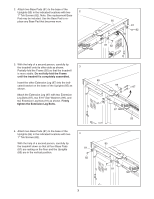
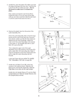
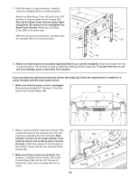
5. Identify the Latch Assembly (76). Make sure that the sleeve has been slid over hole 1 and that the Latch Knob (46) is locked into hole 1. Pull on the sleeve to make sure it is locked into place. Next, make sure that the Latch Knob (46) is locked into hole 2. If it is not, pull out the tube until you see hole 2 and then slide the tube back in until the Latch Knob locks into hole 2. 5 Hole 2 46 Tube Sleeve Hole 1 76 6. Remove the plastic ties from the ends of the Latch Assembly (76). 6 Orient the Latch Assembly (76) so that the large barrel and the Latch Knob (46) are in the positions shown; make sure that all of the holes are aligned (see the inset drawings). Attach the lower end of the Latch Assembly to the bracket in the center of the Uprights (85) with a Latch Bolt (101) and a Nut (20). Then, attach the upper end of the Latch Assembly (76) to the bracket on the Frame (55) with a Latch Bolt (101) and a Nut (20). Note: It may be necessary to move the Frame back and forth to align the Latch Assembly with the Bracket. Lower the Frame (55) (see HOW TO LOWER THE TREADMILL FOR USE on page 26). 55 20 101 76 46 Large Barrel 85 20 101 7. Identify the Left Base Cover (88), which has cutouts in the locations shown. Slide the Left Base Cover onto the left Upright (85). Slide the Right Base Cover (86) onto the right Upright. Identify the Left Upright Sleeve (77) and the Right Upright Sleeve (9). Slide the Upright Sleeves onto the Uprights (85) as shown. 7 Cutouts 85 Left 77 88 Top Holes Holes Bottom Right 9 86 8
-
 1
1 -
2
-
 3
3 -
 4
4 -
 5
5 -
 6
6 -
 7
7 -
 8
8 -
 9
9 -
 10
10 -
 11
11 -
 12
12 -
 13
13 -
14
-
15
-
16
-
17
-
18
-
19
-
20
-
21
-
22
-
23
-
24
-
25
-
26
-
27
-
28
-
29
-
30
-
31
-
32
-
33
-
34
-
35
-
36
 |
 |
