Reebok 8600 Es Treadmill English Manual - Page 9
Sole May Be Damaged When
 |
View all Reebok 8600 Es Treadmill manuals
Add to My Manuals
Save this manual to your list of manuals |
Page 9 highlights
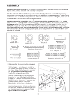
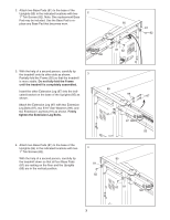
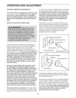
8. Remove the band securing the Upright Wire 8 Harness (73) to the right Upright (85). Have a second person hold the console assembly near the right Upright. Console Assembly Connect the Upright Wire Harness (73) to the wires extending from the console assembly. Make sure to connect the connectors prop- erly (see the inset drawing). The connectors should slide together easily and snap into 73 place. If the connectors do not, turn one connec- tor and try again. IF THE CONNECTORS ARE NOT CONNECTED PROPERLY, THE CON- 85 73 SOLE MAY BE DAMAGED WHEN THE POWER IS TURNED ON. Then, insert the con- nectors into the right Upright (85). 9. Attach the console assembly to the Uprights (85) with four Console Bolts (72) and four 3/8" Star 9 Washers (67) (only one side is shown). Start all four Console Bolts before tightening any of them. 85 10. See drawing 10a. Remove the indicated 3/4" Screw (7) from the right Handrail (70). 10a See drawing 10b. Slide the Right Upright Sleeve (9) up to the console assembly. Attach the Right Upright Sleeve with two 1" Tek Screws (82) and the 3/4" Screw (7) as shown. 70 Attach the Left Upright Sleeve (not shown) in the same way. 7 72 Console 67 Assembly 10b Console Assembly 7 9 82 9
-
 1
1 -
2
-
3
-
 4
4 -
 5
5 -
 6
6 -
 7
7 -
 8
8 -
 9
9 -
 10
10 -
 11
11 -
 12
12 -
 13
13 -
 14
14 -
15
-
16
-
17
-
18
-
19
-
20
-
21
-
22
-
23
-
24
-
25
-
26
-
27
-
28
-
29
-
30
-
31
-
32
-
33
-
34
-
35
-
36
 |
 |
