Reebok Rs 100 Bench English Manual - Page 8
Grease an M10 x 57mm Bolt 26. Attach the Left
 |
View all Reebok Rs 100 Bench manuals
Add to My Manuals
Save this manual to your list of manuals |
Page 8 highlights
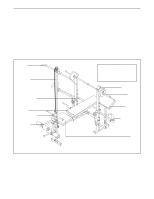
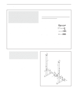
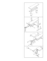
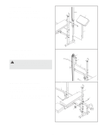
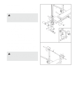
10. Identify the Left Butterfly Arm (6) by the position of the long side of the indicated tube. Slide a Weight Stop (31) onto the Butterfly Arm. Grease an M10 x 57mm Bolt (26). Attach the Left Butterfly Handle (7) to the Left Butterfly Arm (6) with the Bolt and an M10 Nylon Locknut (51). Do not overtighten the Locknut; the Handle must be able to pivot easily. Repeat this step with the Right Butterfly Arm (not shown) and Right Butterfly Handle (not shown). 11. Grease an M10 x 138mm Bolt (45). Attach the Left Butterfly Arm (6) to the indicated Upright (4) with the Bolt and a Butterfly Knob (55). Repeat this step with the Right Butterfly Arm (56). 10 11 56 6 Tube 31 7 26 51 4 45 Grease 55 12. Route the Cable (34) through the Lat Tower (9) 12 and over the Pulley (36). Make sure that the Cable is under the lat rest bar. Attach the Pulley inside the Lat Tower with an M10 x 57mm Bolt (26), two M10 Washers (50), two 7.5mm Spacers (35), and an M10 Nylon Locknut (51). 35 51 50 36 9 34 35 26 50 Lat Rest 13. Insert an M10 x 20mm Bolt (47) into the bracket 13 on the Weight Carriage (10). 9 Slide the Weight Carriage (10) onto the Lat Tower (9). Make sure the bracket on the Weight Carriage and the lat rest on the Lat Tower (see step 12) are on the opposite sides. 34 47 51 Attach the Cable (34) to the M10 x 20mm Bolt (47) with an M10 Nylon Locknut (51). 10 Bracket 8
-
 1
1 -
2
-
 3
3 -
 4
4 -
 5
5 -
 6
6 -
 7
7 -
 8
8 -
 9
9 -
 10
10 -
 11
11 -
 12
12 -
 13
13 -
14
-
15
-
16
-
17
-
18
-
19
 |
 |
