Reebok Vista 8500 Treadmill English Manual - Page 7
If The Connectors Are Not Con
 |
View all Reebok Vista 8500 Treadmill manuals
Add to My Manuals
Save this manual to your list of manuals |
Page 7 highlights
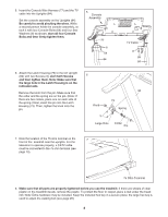
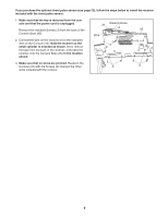
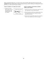
2. With the help of a second person, carefully tip the treadmill onto its other side. Partially fold the Frame (58) so the treadmill is more stable. Do not fully fold the treadmill until it is completely assembled. Attach two Base Pads (82) to the base of the Uprights (84) with two 1" Tek Screws (83) as shown. Insert the other Extension Leg (89) into the base of the Uprights (84) as shown. Hold two Extension Leg Nuts (67) in the bottom of the Extension Leg. Next, insert two Extension Leg Bolts (65) into the top of the Extension Leg, and firmly tighten the Extension Leg Bolts into the Extension Leg Nuts. 2 82 83 84 65 82 67 89 58 3. With the help of a second person, carefully raise the Uprights (84) to a vertical position. 3 Have the second person hold the console assembly near the Uprights (84) as shown. Look under the console assembly and locate the console wire. Remove the band securing the Wire Harness (77) to the right Upright (84). Next, connect the Wire Harness to the Console Wire (66). See the inset drawing. The connectors should slide together easily and snap into place. If the con- 66 nectors do not slide together easily and snap into place, turn one connector and then try again. IF THE CONNECTORS ARE NOT CON- 77 NECTED PROPERLY, THE CONSOLE MAY BE DAMAGED WHEN THE POWER IS TURNED ON. 4. Look under the console assembly and locate the TV cable. 4 Remove the band securing the Upright TV Cable (104) to the left Upright (84). Connect the Upright TV Cable to the TV cable on the console assembly. Console Assembly 66 77 84 Console Assembly TV Cable 104 84 7
-
 1
1 -
 2
2 -
 3
3 -
 4
4 -
 5
5 -
 6
6 -
 7
7 -
 8
8 -
 9
9 -
 10
10 -
 11
11 -
 12
12 -
13
-
14
-
15
-
16
-
17
-
18
-
19
-
20
-
21
-
22
-
23
-
24
-
25
-
26
-
27
-
28
-
29
-
30
-
31
-
32
-
33
-
34
-
35
-
36
 |
 |
