Rheem M8350ti Installation Instructions - Page 10
Controls & Indicator Lamps, Analog Models - heat pump
 |
View all Rheem M8350ti manuals
Add to My Manuals
Save this manual to your list of manuals |
Page 10 highlights
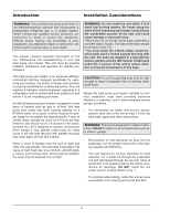
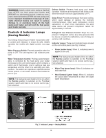
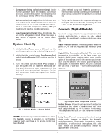
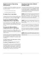
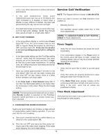
WARNING: Install a check valve and/or a Hartford loop AFTER the heat pump pool heater and BEFORE any chlorinating devices. Install any automatic chemical feeders AFTER the heat pump pool heater. Improper installation of any type of automatic chemical feeders can result in serious damage to, or premature failure of, the heat pump pool heater and will void the heat pump pool heater warranty. Controls & Indicator Lamps (Analog Models) Your analog heat pump pool heater incorporates safety controls and indicators to ensure its safe, reliable operation (for models with digital controls, see page 11). Water Pressure Switch: Prevents operation when the pump is OFF. The unit requires 5 psi minimum pressure. Water Temperature Control: Pool/spa water temperature is controlled by the heat pump pool heater thermostat on the unit control panel, which contains a switch and 2 thermostats, one for setting a heat spa temperature and the other for a swimming pool temperature. The switch can operate an optional external control system, or can switch between thermostats for pool or spa. NOTE: The heat pump pool heater will not run when the Remote position is selected on the Pool/Spa selector switch and there is no remote control system attached. Defrost Switch: Prevents heat pump pool heater operation if ambient air temperature falls below a predetermined safe minimum (approximately 42° F). Delay Timer: Prevents compressor from short cycling, which could damage or destroy the hermetic motor/compressor. Upon water temperature control satisfaction, or other circuit interruptions, this solid state device will prevent compressor restart for approximately 5 minutes. Refrigerant Low Pressure Control: Stops the compressor if refrigerant suction (low side) pressure falls too low as a result of a malfunction, loss of charge or extreme cold conditions. Indicator Lamps: There are 6 indicator lamps located on the unit control panel (see Fig. 3 below): • Power (amber lamp): When lit, indicates power is applied to the unit. NOTE: The heat pump pool heater will not run when the Remote position is selected on the Pool/Spa selector switch and there is no remote control system attached. • Water Flow (green lamp): When lit, indicates normal water flow. • Heat Demand (green lamp): When lit, indicates the actual water temperature is below the target water temperature. Fig. 3: Indicator Lamps - Analog Models 10
-
 1
1 -
2
-
3
-
4
-
 5
5 -
 6
6 -
 7
7 -
 8
8 -
 9
9 -
 10
10 -
 11
11 -
 12
12 -
 13
13 -
 14
14 -
 15
15 -
16
-
17
-
18
-
19
-
20
-
21
-
22
-
23
-
24
-
25
-
26
-
27
-
28
 |
 |