Rheem M8350ti Installation Instructions - Page 9
Water Connections, Pressure Drop - model
 |
View all Rheem M8350ti manuals
Add to My Manuals
Save this manual to your list of manuals |
Page 9 highlights
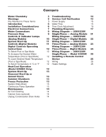
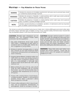
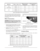
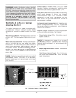
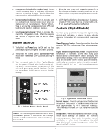
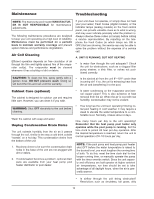
Model No. 5350 6350/6350HC 8350 VAC in - Phase - Hz 208/230 - 1 - 60 208/230 - 1 - 60 208/230 - 1 - 60 208/230 - 3 - 60 Minimum Circuit Ampacity (A) 40.0 42.0 42.0 34.0 Maximum Breaker Size (A) 60 60 60 50 Table A: Typical System Electrical Power Requirements This unit is pre-wired to work with external control systems, heat-on-demand options and other external time clock overrides. Refer to the external control system's instructions, and page 26 of this manual, for installation information. the purpose and, in either case, should be at least equal in size to the main pool/spa circulation piping. Water Connections CAUTION: The heat pump pool heater inlet and outlet connections are NOT interchangeable. They must be connected as instructed below. WATER IN WATER OUT 1. Connect the heat pump pool heater in the return water line between the filter and the pool/spa. See the Plumbing Diagrams beginning on page 16. 2. Connect the filter outlet to the fitting marked WATER IN at the bottom front of the unit. 3. Connect the fitting marked WATER OUT to the return piping to the pool/spa. Unit inlet/outlet connection fittings are 2-inch PVC unions. Fig. 2: Water Connections 4. In cold weather (freeze zone) areas, shutoff valves (ball or gate type) must be installed at the unit inlet and outlet to facilitate service and cold weather drain-down. 5. Operate the pump and check the system for leaks. Pressure Drop Water connections from the unit to the main return For system pressure drop information, refer to Table B line can be PVC pipe or flexible pipe approved for below. Flow (gpm) 30 40 50 60 70 80 5350 4 7 10 11 12 13 Pressure Drop (psi) 6350/6350HC 6 9 10 11 12 13 8350 9 9 10 11 12 13 Note: Multiply the pressure drop in psi by 2.3067 to yield the pressure drop in Ft. H2O Head (TDH). Table B: Pressure Drop Across Heat Pump Pool Heater 9
-
 1
1 -
2
-
3
-
 4
4 -
 5
5 -
 6
6 -
 7
7 -
 8
8 -
 9
9 -
 10
10 -
 11
11 -
 12
12 -
 13
13 -
 14
14 -
15
-
16
-
17
-
18
-
19
-
20
-
21
-
22
-
23
-
24
-
25
-
26
-
27
-
28
 |
 |