Rheem M8350ti Installation Instructions - Page 7
Electrical Connections
 |
View all Rheem M8350ti manuals
Add to My Manuals
Save this manual to your list of manuals |
Page 7 highlights
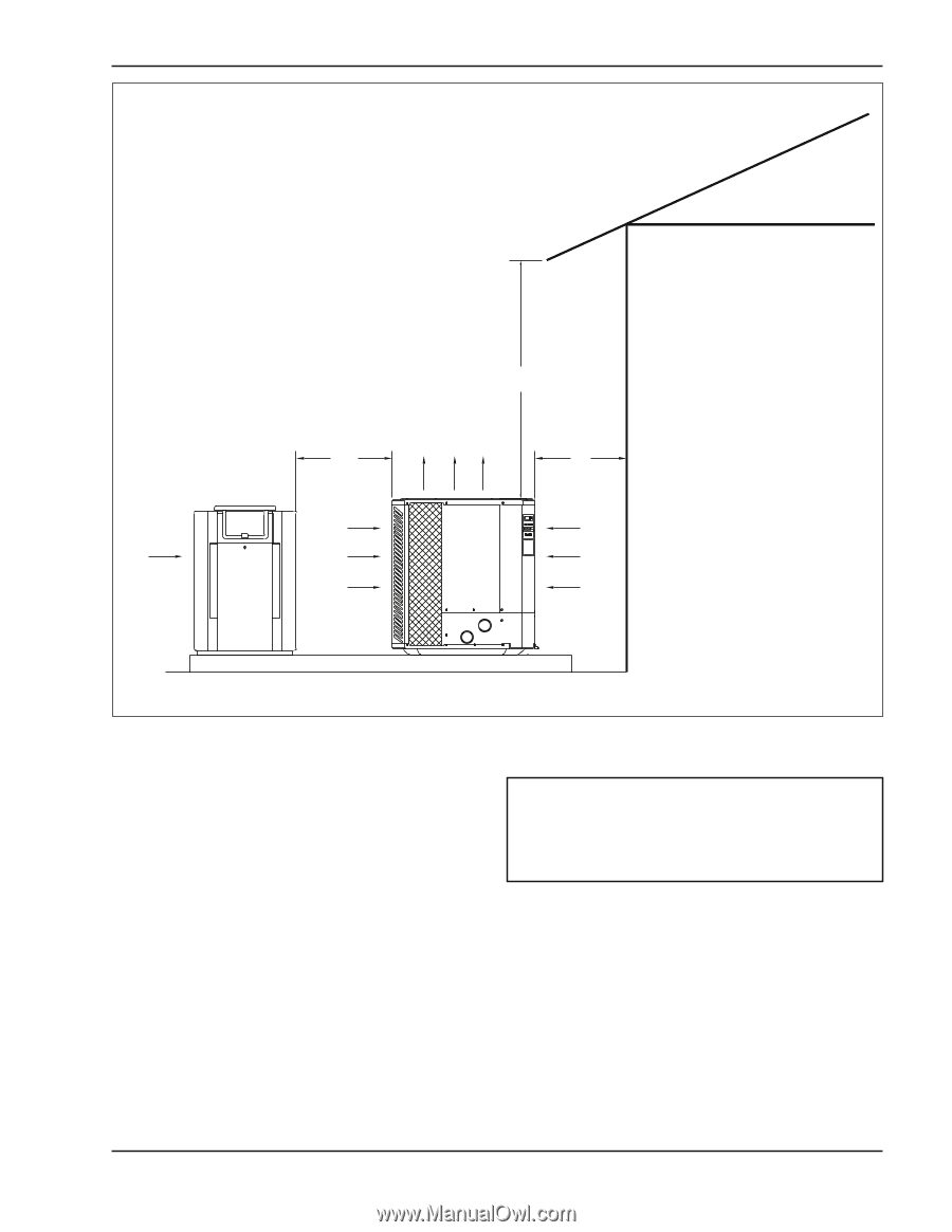
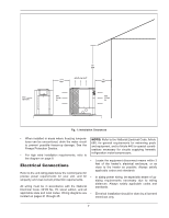
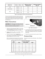
GAS HEATER 3 FT MIN 60" MIN AIR FLOW OUT 12" MIN AIR FLOW IN AIR FLOW IN Fig. 1: Installation Clearances • When installed in areas where freezing temperatures can be encountered, drain the water circuit to prevent possible freeze-up damage. See the Freeze Protection Section. • For high wind installation requirements, refer to the diagram on page 8. Electrical Connections Refer to the unit rating plate below the control panel for precise power requirements for your unit, and for ampacity and over-current protection requirements. All wiring must be in accordance with the National Electrical Code, NFPA No. 70, latest edition, and all applicable state and local codes. Wiring diagrams are located on pages 21 through 25. NOTE: Refer to the National Electrical Code, Article 680, for general requirements for swimming pools and equipment, and to Article 440 for special considerations necessary for circuits supplying hermetic refrigeration motor/compressors. • Locate the equipment disconnect means within 3 feet of the heater's electrical enclosure, or as close to the heater as possible. Always satisfy applicable codes and standards. • In sizing power wiring, be especially aware of upsizing requirements necessary due to wiring distances. Always satisfy applicable codes and standards. • Electrical installation should be done by a licensed electrician only. 7
-
 1
1 -
 2
2 -
 3
3 -
 4
4 -
 5
5 -
 6
6 -
 7
7 -
 8
8 -
 9
9 -
 10
10 -
 11
11 -
 12
12 -
13
-
14
-
15
-
16
-
17
-
18
-
19
-
20
-
21
-
22
-
23
-
24
-
25
-
26
-
27
-
28
 |
 |