Rheem Versa Spa Heaters Operating Instructions - Page 25
Heat Exchanger Removal, De-sooting Procedure, Combustion Chamber Removal, Control Immersion Well,
 |
View all Rheem Versa Spa Heaters manuals
Add to My Manuals
Save this manual to your list of manuals |
Page 25 highlights
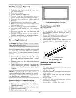
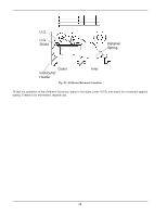
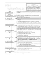
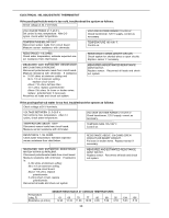
Heat Exchanger Removal 1. Shut water, gas, and electricity off, close valves and relieve pressure. 2. Drain heat exchanger. 3. Loosen and remove flange bolts. 4. Remove flange and inlet/outlet pipes from the header. Remove drain valve from rear header. 5. Remove outdoor stackless top or indoor stack top from unit. 6. Remove jacket top, flue collector, and baffle. 7. Remove upper front jacket panel, and disconnect wires at toggle switch. 8. Remove capillary bulb from inlet/outlet header. 9. Disconnect press switch tube from inlet/outlet header. 10. Disconnect high limit wire from thermostat, and pressure switch. 11. Lift heat exchanger straight up from combustion chamber, using caution not to damage refractory. 12. Reverse above procedure to reinstall. De-sooting Procedure CAUTION: Soot is combustible. Exercise extreme care. Never use a wire brush. Fig. 29: Refractory Panel-Top View Control Immersion Well Replacement 1. Remove plumbing and top portion of unit (See Heat Exchanger Removal procedure, steps 1 through 6). 2. Remove U.G. spring, U.G. and copper shield. 3. Collapse well tube at open end with chisel. 4. Push well up through header. 5. Insert new well and roll in place. If a roller is not available, solder the well in place with silver solder. Soot can clog areas between fins and cause eventual tube failure. Any sign of soot at the base of the burners or around the outer jacket indicates a need for cleaning. 1. Disconnect top portion of unit. (See Heat Exchanger Removal procedure steps 1 through 6). 2. Remove burner tray (See Burner tray Removal procedure.) 3. Take a garden hose and wash heat exchanger, making sure soot is removed completely from between fins. Avoid excessive water against refractory. NOTE: In extreme cases it may be necessary to remove the heat exchanger completely for cleaning. The simplest method is steam cleaning at the local car wash. DO NOT WIRE BRUSH. Combustion Chamber Removal 1. Remove heat exchanger (See Heat Exchanger Removal procedure). 2. Lift up and remove front and rear refractory shield. 3. Remove refractory panels. 4. Reverse above procedure to reinstall. Immersion Well Fig. 30: Immersion Well Unitherm Governor (U.G.) Replacement 1. Shut water, gas and electricity off, close valves and relieve pressure. 2. Drain heat exchanger. 3. Disconnect inlet and outlet pipes with flange from in/ out header. 4. Grasp retainer spring from inlet side of header, and slide thru inlet hole. 5. Remove shield. 6. Remove U.G. with seating gasket, and stainless steel baffle (not shown). 7. Reverse above procedure to re-install. 25
-
 1
1 -
2
-
3
-
4
-
5
-
6
-
7
-
8
-
9
-
10
-
11
-
12
-
13
-
14
-
15
-
16
-
17
-
18
-
19
-
 20
20 -
 21
21 -
 22
22 -
 23
23 -
 24
24 -
 25
25 -
 26
26 -
 27
27 -
 28
28 -
 29
29 -
 30
30 -
31
-
32
-
33
-
34
-
35
-
36
 |
 |
