Ricoh Pro C550EX Quick Installation Guide - Page 1
Ricoh Pro C550EX Manual
 |
View all Ricoh Pro C550EX manuals
Add to My Manuals
Save this manual to your list of manuals |
Page 1 highlights
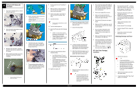
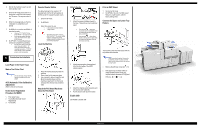
Quick Installation Guide D014/D015 1 Checking the Installation Area 1. Temperature Range Recommended Temp.: 23°C (73.4°F) Allowed Temp.: 10°C to 32°C (50°F to 90°F) 2. Humidity Range: 15% to 80% Rh 2 Checking the Supplied Accessories Check the accessories and their quantities against the following list: 1. Instructions Pocket (1) 2. Exposure glass cloth holder (1) 3. Exposure glass cloth (1) 4. Leveling shoes (4) 5. PCU stand (1) 6. Ferrite Core (1) 7. PCU Stand Holder (1) 8. Paper Loading decal 9. Paper size decal 3. Machine Level Make sure the machine meets the following level requirements: Front to rear: Less than5mm(0.2")variance Righttoleft:Lessthan5mm(0.2")variance 4. Minimum Space Requirements Put the copier near the power source. Minimum clearance must be as shown below. The same amount of clearance is necessary when optional peripheral devices are installed. 3 Shipping and Packing Material 1. Remove Shipping Tape and Packing Material 5. Check the power source The power requirements for this model are as follows: North America D014 -120V 60Hz, more than 16A D015 -208 to 240V 60Hz, more than 12A Warning Make sure the wall outlet is near the machine and that you have easy access to it. Make sure the plug is tightly connected to the outlet. Do not connect more than one electrical device to the same outlet as the copier is connected to. Be sure the outlet is grounded Do not rest objects on the power cord Warning Make sure the power cord is disconnected from the wall outlet during this procedure Remove the following shipping and packing material: A. ARDF, right side B. Packing block inside ARDF C. Accessories bags (Trays1, 2, and 3) D. ARDF, left side E. ARDF connector cord. Remove tape and connect the cord F. Power cord Remove the following shipping and packing material: A. Under ARDF B. Operation panel film 3. From Tray 1 remove: A. Block and tape B. Retainer, tag, and wire 4. Remove all retainers and accessories from Tray 2 and 3 2. Shipping Retainer Removal 8. Remove the tag, and rod [A] (x 1). 9. Disconnect the fan connector [B]. 10. Remove the faceplate [C] (x 5). 1. Open the front door 2. Remove the transfer belt release lever [A] (1 tape). This will be installed in the correct location later. Do not touch [B], [C], or [D] at this time. They will be removed after the faceplate is removed. To prevent damage to the ITB, remove the rod with the red tag [B] BEFORE you turn down the lever [D] and attempt to pull out the drawer. The drawer must remain in the machine until after the developer is installed in the developer cartridges of the PCUs. The rod is removed AFTER the faceplate is removed. 1. Prepare an open space on the floor for the hopper. 2. Remove the screws of the hopper cover [A] (3). 3. Put your hands under the left and right corners of the toner hopper, and slowly pull it out on its rails until it stops. 4. Push the lock [B] then pull down the support leg [C]. 5. Make sure that the support leg is down and locked in place before you remove the hopper. 6. Hold the toner hopper using the handles at the top left and right sides, then lift the hopper off its rails and set on the floor. Warning Always make sure the support leg is down and locked before you remove the hopper. The hopper is heavy! Lift it carefully and make sure that it disengages fully from the rails on the left and right. 7. Push the rails back into the machine Do not pull out the drawer unit until after you remove the stabilizing rod and tag. 11. Pull on the reinforced ring of the red tag to pull out the stabilizing rod [A]. 3. Reattach The Faceplate 1. Attach the faceplate [A] with the screws in the sequence shown by the numbers above (x 5). Do not tighten these screws too much. 2. Reattach the fan [B]. Page 1 of 3 4. Remove Remaining Retainers and Packing Materials 1. Turn the lever [A] down to the left, and pull the drawer unit [B] out of the machine until it stops. 2. Remove the instruction sheets [C] and [D]. A sheet of paper protects the ITB if you accidentally pull the drawer out without first removing the rod. Do not push the drawer into the machine. Follow the procedure on the instruction sheet to remove the rod and paper. 3. Raise lever D2 [A] of the fusing unit. 4. Turn knob D1 [B] in the direction shown by the arrow. 5. Remove protective sheet [C] with tape and red tag. 6. Lower lever D2 [A]. 7. Push the drawer into the machine until it stops. 8. Rotate handle B2 up and to the right until it stops.
-
 1
1 -
 2
2 -
 3
3
 |
 |
