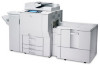
Ricoh Pro C550EX Quick Installation Guide - Page 3
Load Paper in the Paper Trays - manual
 |
View all Ricoh Pro C550EX manuals
Add to My Manuals
Save this manual to your list of manuals |
Page 3 highlights
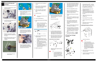
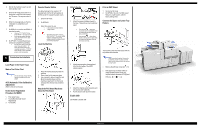
4. Wait for the machine to warm up and enter standby mode. 5. Enter the SP mode and do 3811-1 to send toner to the PCUs and initialize the TD sensor. This requires about 4 min. 6. When the message tells you that the initialization is completed, touch [Close]. 7. Do SP3812-1 to confirm that SP3811-1 executed correctly. If you see "1111" (K M C Y), this means SP3811-1 executed correctly. If you see any number other than "1111", this means an error. (See SP3812 Errors.) 8. Do SP 3821-1 to check that process control was completed successfully. For each color, there is a two-digit code, in the order K,M,C,Y. '10' means that process control was completed successfully. '10101010' means that all 4 colors completed process control successfully. 5 Completing the Installation Load Paper in the Paper Trays Make a Test Color Print Use the same type of paper that the customer normally uses for color outputs. ACC (Automatic Color Calibration) Adjustment (Refer to the service manual) Do the Color Registration Procedure for MUSIC 1. Push [User Tools]. 2. Touch [Maintenance]> [Color Registration]. 3. Touch [OK]. Counter Display Setting The default setting for the counter is "0" (development). Do the SP setting below to set the counter for copy/print (paper count). 1. Enter the SP mode. 2. Do SP5045-1. 3. Select the counter to use: 0: Development counter (Default) 1: Page counter This setting can be done only once. After it is set to "1", the counter setting cannot be changed. If the wrong setting is selected by mistake, contact your technical supervisor Level the Machine 1. Place the leveling shoes [A] under the machine. 2. Place a level on the exposure glass. 3. Use a wrench to raise or lower the nuts [B] on the leveling shoes until the machine is less than 5 mm from level (measure from front-to-rear and left-toright). Attach the PCU Stand Rack and Store the PCU Stand Attach Decals 1. Attach the paper-installation decals to the trays. These tell you how to add new paper. Front set decal : Attach this decal to the LCT if it is installed. 'Front set' means that the paper should be face up in the tray. Back set decal : Attach these decals to the trays of the copier. 'Back set' means that the paper should be face down in the tray. 2. Attach exposure-glass-cleaning decal [A] at the front edge of the ARDF exposure glass. 3. Attach the original-caution decal [A], and the silicone cloth holder [B]. 4. Put the silicone cloth [C] in the holder. Enable USB Do SP5985 to enable USB. Print an SMC Report 1. Go into the SP mode. 2. Do SP5990-1 to print a full SMC report. Keep it in a safe location, with the factory setting sheet. Connect the Upper and Lower Tray Heaters The machine comes from the factory with the tray heaters disconnected. Heater connection is optional. Connect the heaters if the location is extremely humid. Speak with the customer before you connect the tray heaters. 1. Remove the left lower cover [A] ( x 5). 2. If the paper tray unit heater (HTS) or image transfer/scanner heater are required, attach connectors HT5 [B] and HT6 [C] ( x 1, x2) Page 3 of 3
-
 1
1 -
 2
2 -
 3
3
 |
 |
