Ridgid EB4424 Owners Manual - Page 12
Assembly - sander parts
 |
View all Ridgid EB4424 manuals
Add to My Manuals
Save this manual to your list of manuals |
Page 12 highlights
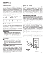
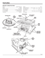
ASSEMBLY WARNING: Do not connect to power supply until assembly is complete. Failure to comply could result in accidental starting and possible serious personal injury. MOUNTING RUBBER FEET TO BASE See Figure 5. n Place the sander directly on the table surface. n From the parts bag locate the four rubber feet. n Place the sander on its side so the bottom of the base is facing toward the front. n Locate the four holes in each corner of the base and place one of the rubber feet in each of these holes. n Position sander in the upright position and apply pressure in the downward position to ensure the feet are inserted securely. CAUTION: To reduce the risk of injury from tool movement, the supporting surface where sander is mounted should be examined carefully after mounting to insure no movement during use can result. If any tipping or walking is noticed, secure to workbench or supporting surface before operating sander. moUNTING SANDER To Workbench See Figure 6. If sander is to be used in a permanent location, it should be fastened securely to a firm supporting surface, such as a workbench, with either bolts or drywall screws. Fastening with bolts n Use 1/4 in. bolts, washers, and nuts (not included). The bolt length should be 1-1/2 in. plus the thickness of the workbench. n Locate and mark the holes where the sander is to be mounted. n Drill four 3/8 in. diameter holes through workbench. n Place sander on workbench, aligning holes in base with holes drilled in workbench. n Insert four 1/4 in. diameter bolts and washers and attach nuts securely. Fastening with screws n Drive four 2-1/2 in. long screws through the holes in the base and through the workbench. Do not overtighten the screws. BASE HOLE REMOVE 2-1/2 in. DRYWALL SCREW WASHER NUT RUBBER FEET Fig. 5 1/4 in. BOLT Fig. 6 12
-
 1
1 -
2
-
3
-
4
-
5
-
6
-
 7
7 -
 8
8 -
 9
9 -
 10
10 -
 11
11 -
 12
12 -
 13
13 -
 14
14 -
 15
15 -
 16
16 -
 17
17 -
18
-
19
-
20
-
21
-
22
-
23
-
24
-
25
-
26
 |
 |
